Defining the rc-52a room controller rear panel – Kramer Electronics RC-52A User Manual
Page 7
RC-52A –
Overview
5
3.2
8B
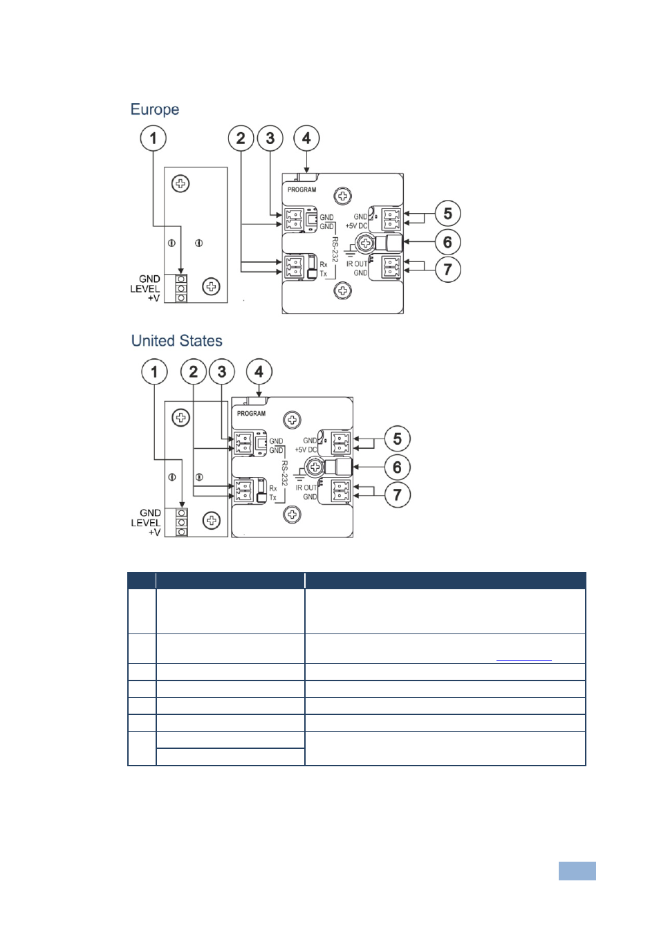
Defining the RC-52A Room Controller Rear Panel
Figure 2: RC-52A Rear Panel for Europe (80 and 86mm) and the United States
#
Feature
Function
1 Audio Potentiometer pinout GND PIN: ground connection for the potentiometer
LEVEL PIN: wiper of the potentiometer
+V: +10V connection of the potentiometer
2 RS-232 Terminal Block
Connector
Connect to the RS-232 connector on the A/V equipment
or a PC or other Serial Controller, see
U
Section 4.1
3 GND PIN
Not used
4 PROGRAM USB Connector Connect to a computer for unit configuration
5 GND PIN
Connects (-) to the Ground
6 +5V PIN
Connects (+) to the connector for powering the unit
7 IR OUT PIN
Connect to an IR emitter cable
GND PIN
See also other documents in the category Kramer Electronics Accessories for electrical:
- VM-114H (22 pages)
- VM-114H2C (25 pages)
- VM-114H4C (23 pages)
- VS-81ETH (27 pages)
- VS-81ETH (41 pages)
- VM-9T (13 pages)
- VP-12NHD (15 pages)
- VP-5R (20 pages)
- VP-6A (15 pages)
- PT-5R/T (13 pages)
- TP-102HD (13 pages)
- TP-104HD (33 pages)
- TP-112HD (13 pages)
- TP-114 (13 pages)
- TP-202 (15 pages)
- TP-205A (15 pages)
- TP-210 (14 pages)
- TP-210A (15 pages)
- tp-219hd (16 pages)
- TP-305A (15 pages)
- TP-310A (18 pages)
- TP-410 (34 pages)
- VM-1H4C (17 pages)
- VP-200xlT (31 pages)
- VP-300THD (12 pages)
- VPM-2 (42 pages)
- SI-1VGA (2 pages)
- SID-DP (2 pages)
- SID-DVI (2 pages)
- SID-H (2 pages)
- SID-VGA (2 pages)
- SID-X1 (2 pages)
- SID-X1 (23 pages)
- SID-X1N (23 pages)
- SID-X2N (31 pages)
- SID-X3N (22 pages)
- 622R (17 pages)
- VS-169TP (7 pages)
- VS-169TP (45 pages)
- WSI-1VGA (2 pages)
- TP-107AV (32 pages)
- WP-500 (2 pages)
- SV-552 (22 pages)
- WP-501 (16 pages)
- RC-62 (94 pages)