Figure 7: blend width incorrectly adjusted – Kramer Electronics VP-790 User Manual
Page 10
8
VP-790 Blending Images - Setting Blend Width
•
Line 1 is the left hand edge of the right hand projection
•
Line 2 is the right hand edge of the left projection blend region
•
Line 3 is the left hand edge of the right projection’s blend region
•
Line 4 is the right hand edge of the left hand projection
Referring to
above, adjust line 3 to meet line 1 and adjust line 2 to meet
line 4. This adjusts the blend width of each projector so that the shadowed
alignment area is equal to the optical overlap.
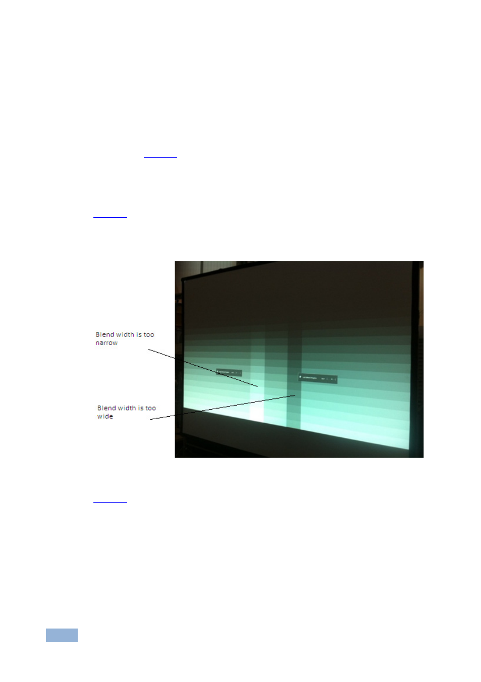
shows a darker vertical strip on the right hand side where the blend width
has been adjusted past the overlap (blend width is too wide) and on the left hand
side a lighter vertical strip showing a blend width that is too narrow.
Figure 7: Blend Width Incorrectly Adjusted
shows the view when the blend widths on both Scalers are adjusted
correctly.