Kramer Electronics VP-770 User Manual
Page 14
VP
-7
7
0
–
Ov
e
rv
ie
w
9
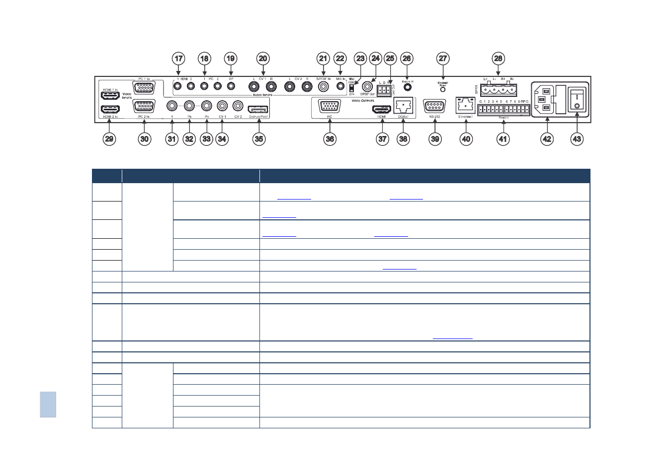
Figure 2: VP-770 Presentation Switcher/Scaler Rear Panel
#
Feature
Function
17
AUDIO IN
Unbalanced
Connectors
HDMI 3.5mm Mini Jack
Connect to an unbalanced audio source for audio takeover of the HDMI 1 and HDMI 2 embedded audio
(see
Section
). The pinout is defined in
Section
18
PC 3.5mm Mini Jack
Connect to the unbalanced audio of the computer graphics source (from 1 to 2). The pinout is defined in
Section
19
DP 3.5mm Mini Jack
Connect to the unbalanced audio source for analog audio takeover of the DisplayPort embedded audio (see
Section
). The pinout is defined in
Section
20
CV (L, R) RCA
Connect to the unbalanced stereo audio of the composite video source (from 1 to 2)
21
S/PDIF IN RCA
Connect to the digital audio source of the component video (Y, Pb, Pr)
22
MIC IN 3.5mm Mini Jack
Connect to a microphone (see pinout in
Section
23
COND/DYN MIC DIP-switch
Select between a condenser and a dynamic type microphone
24
S/PDIF OUT RCA Connector
Connect to a digital audio acceptor
25
LINE OUT (L, R) Terminal Block Connector Connect to the L and R unbalanced stereo audio acceptor
26
REMOTE IR 3.5mm Mini Jack (opening)
Covered by a cap. The 3.5mm connector at
the end of the internal IR connection cable
fits through this opening
Connects to an external IR receiver unit for controlling the machine via an IR remote controller (instead of
using the front panel IR receiver)
Optional. Can be used instead of the front panel (built-in) IR receiver to remotely control the machine (only if
the internal IR connection cable has been installed)
,
see
Section
27
ETHERNET RESET Button
Press while turning power off and then on, to reset the Ethernet settings to their factory default state
28
SPKR Terminal Block Connector
Connect to a balanced stereo audio acceptor (speakers)
29
VIDEO INPUT
Connectors
HDMI
Connect to the HDMI source (from 1 to 2)
30
PC 15-pin HD
Connect to the computer graphics source (from 1 to 2)
31
Y RCA
Connect all three connectors to the component video source
32
PB RCA
33
PR RCA
34
CV RCA
Connect to the composite video source (from 1 to 2)