2 defining the inputs, 3 defining the windows, Defining the inputs – Kramer Electronics VP-747 User Manual
Page 12: Defining the windows, Figure 7: input button, N 3.2, On 3.3
10
VP-747 Control Software - Defining the Control Software
3.2
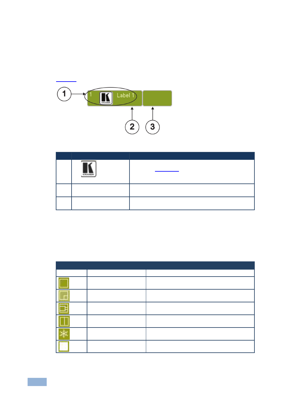
Defining the Inputs
The Input area consists of 8 buttons for each channel that are divided into Preview
and Program buttons.
shows a typical input button.
Figure 7: Input Button
#
Feature
Description
1
1
Label 1
Input channel number, user-selectable icon and button
label (see
Section 5.3
2
), background color indicates the
status of the input/output: green—active, white—
inactive
Preview Button
Click this button to display the chosen channel on the
Preview output
3
Program Button
Click this button to display the chosen channel on the
Program output
3.3
Defining the Windows
The Windows area contains the Preview and Program PIP input dropdowns, the
screen display presets and the PIP preview windows.
Button
Button Name
Description
PIP Input
Chooses the PIP source from channels 1 to 8
Preset Full
Switches to a full-screen output
Preset PIP
Switches to a picture-in-picture output
Preset Pic+Pic
Switches to a picture-and-picture output
Preset Split
Switches to a split screen output
Freeze Window
Freezes the output display
Set visibility of window
Blanks/shows the output display