Table 1, Your tp-210 xga line transmitter/da – Kramer Electronics TP-210 User Manual
Page 8
KRAMER: SIMPLE CREATIVE TECHNOLOGY
Your TP-210 XGA Line Transmitter/DA
6
Table 1: Front Panel TP-210 XGA Line Transmitter/DA Features
#
Feature
Function
1
POWER Switch
Illuminated switch for turning the unit ON or OFF
2
XGA INPUT 15-pin HD Connector
Connects to the video source
3
XGA OUT 2 15-pin HD Connector
Connects to the video acceptor 2
4
XGA OUT 1 15-pin HD Connector
Connects to the video acceptor 1
5
OUT CAT 5 Connectors
Connect to the LINE IN connectors of Line Receivers
(from 1 to 10)
6
Power Connector with FUSE
AC connector enabling power supply to the unit
The TP-210 underside is illustrated in
and defined in
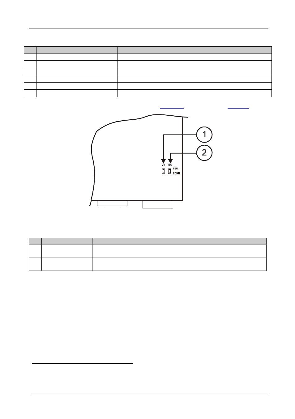
Figure 2: TP-210 XGA Line Transmitter/DA Underside View
Table 2: TP-210 XGA Line Transmitter/DA Underside Features
#
Feature
Function
1
VS Switch
To retain the polarity, slide the switch down
(to NORM.);
to change the VS polarity to negative polarity, slide the switch up (to NEG.)
2
HS
Switch
To retain the polarity, slide the switch down
(to NORM.);
to change the HS polarity to negative polarity, slide the switch up (to NEG.)
1 Using a cable with CAT 5 connectors at both ends
2 By default, both switches are set to NORM