2 pneumatic installation, Connections for the compressed air supply, 3 installing circuitry – Festo Неполноповоротные приводы Sypar DAPS User Manual
Page 3: 8 commissioning, 1 adjustment of the end positions
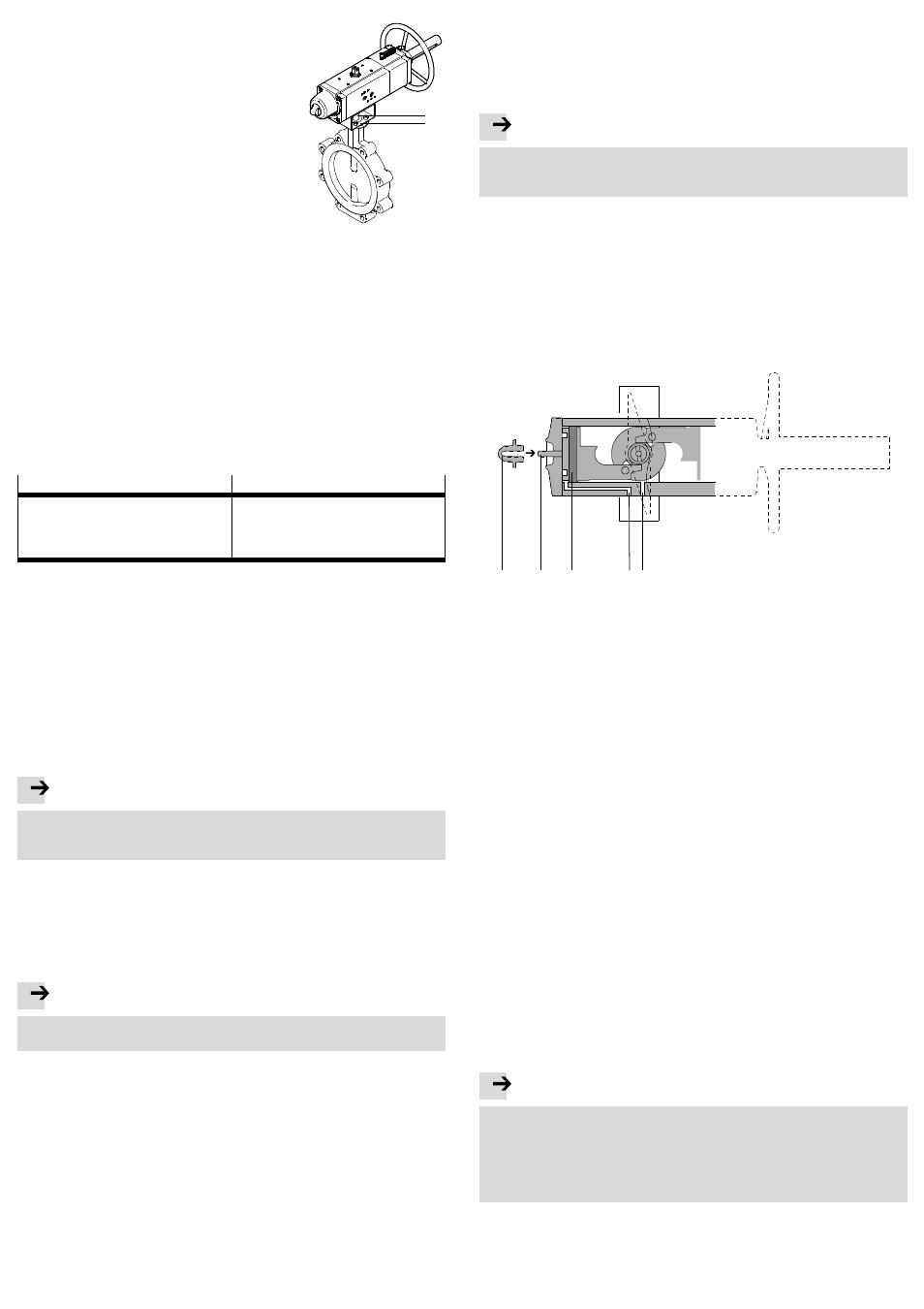
To mount the quarter turn actuator with an adapter
bridge, you need:
Fig. 10
1
2
– an adapter bridge (
Fig. 10,
1 ),
– a shaft extension (
Fig. 10,
2 ).
1. Align the adapter bridge so that its supports are
oriented in the direction of the longitudinal axis of
the quarter turn actuator and, if necessary, the
open side of the adapter bridge towards the pro-
cess valve.
2. Fasten the adapter bridge to the quarter turn actu-
ator. Do not yet tighten the screws.
3. Guide the shaft extension through the adapter
bridge into the star-shaped coupling on the bot-
tom of the quarter turn actuator. Make sure that
the shaft extension sits in the coupling without
being tilted.
4. Fasten the quarter turn actuator with adapter bridge and shaft extension to the
connection flange of the process valve. Make sure here that the square of the
processing valve sits in the shaft extension without being tilted.
5. Tighten all the screws in diagonally opposite sequence.
Tightening torque
Fig. 8.
After fitting the quarter turn actuator:
6. Check that the quarter turn actuator turns in the required direction of rotation
and whether the processing valve assumes the required position.
7. If the quarter turn actuator does not turn in the required direction of rotation:
Carry out the following modification:
DAPS..R-… (double-acting)
DAPS..RS-… (single-acting)
1. Remove the pneumatic solenoid valve.
2. Turn the solenoid valve 180°.
3. Note the position of the threaded pin for
orientation of a NAMUR valve.
4. Fasten the solenoid valve again.
1. Remove the screws on the actuator side.
2. Turn the actuator 90° while it is still connec-
ted through the shaft extension or directly to
the processing valve.
3. Tighten the mounting screws.
7.2 Pneumatic installation
Connections for the compressed air supply
• DAPS quarter turn actuator, double-acting – standard design
– Air supply at port 2 (A) – see Fig. 1
2
Rotation of the switching shaft in an anti-clockwise direction.
– Air supply at port 4 (B) – see Fig. 1
4
Rotation of the switching shaft in a clockwise direction.
• DAPS quarter turn actuator, single-acting with spring return – standard design
– Air supply at port 4 (B): rotational movement anti-clockwise.
– Spring return: rotation clockwise.
Note
For DAPS..RS-… (single-acting):
• Fasten a filter element to the exhaust port 2 (A) to prevent ingress of dirt
particles.
7.3 Installing circuitry
Using the pneumatic switching valves:
• Please note the instructions and explanations in the relevant operating instruc-
tions for the pneumatic valves.
8
Commissioning
Note
• Make sure that the operating conditions
section 12 lie within the permissi-
ble ranges.
The product is ready for operation as soon as it is installed and connected.
• Make sure that a process valve attached to the quarter turn actuator can be
switched without hindrance.
• When the supply pressure is switched off, set the handwheel to the neutral
position (
Fig. 5) so that the actuator can be operated pneumatically.
• Slowly pressurize the quarter turn actuator.
8.1 Adjustment of the end positions
Some product variants offer the possibility to adjust one or even both end posi-
tions of the DAPS within narrow limits in order to influence the closing or opening
angle of the mounted process valve. During adjustment of the end positions, ob-
serve the permissible adjustment range of the DAPS used (
section 12, end
position adjustment range).
Note
Product variants without specification of an adjustment range have
no possibility
for setting end positions, e.g. all product variants made of stainless steel
(DAPS-...-CR).
The now following description for end position setting refers to the following sizes
in the designs “Standard” and “Low temperature” (-T6):
– DAPS-…-R-…(double-acting); size 0015 up to 1920 (
section 8.2)
– DAPS-…-RS.. (single-acting); size 0015 up to 0960 (
section 8.3)
Information on adjustment of the end position for other sizes can be found, if ap-
plicable, in the appendix to the operating instructions supplied with the product
(
www.festo.com).
8.2 Adjustment for the DAPS-…-R-… (double-acting) – size 0015 … 1920
For these product variants, the end position that the actuator takes during venting
through port 4 (B) can be adjusted (turn to the right - close process valve).
1
2
3
5
4
1 Lock nut with sealing ring
2 Threaded rod
3 Piston
4 Port 2 (A)
5 Port 4 (B)
Fig. 11
1. Supply compressed air and close the process valve. The pistons move to the
outer end position. This fixes the threaded rod – dependent on the current set-
ting. Loosening of the lock nut will then not accidentally change the current
setting.
2. Screw down the lock nut with sealing ring. If the threaded rod has loosened,
retighten it by hand until a light resistance is felt.
3. Supply compressed air and open the process valve. The pistons move to the
inner end position.
4. Adjust the end position:
Observe that a complete turn of the threaded rod can change the swivel angle
approx. 1.5° to 3.5° – dependent on the product design.
– Turning the threaded rod clockwise reduces the swivel angle.
– Turning the threaded rod anti-clockwise increases the swivel angle.
5. Supply compressed air and close the process valve. The pistons run against the
threaded rod into the outer end position.
6. Check the position of the process valve. To change the swivel angle, repeat
step 3 and 4.
7. Retighten the lock nut on the threaded rod – tightening torque 5 Nm.
8. Check the mode of operation of the quarter turn actuator (
section 8.4)
8.3 Adjustment with the DAPS-…-RS.. (single-acting) – size 0015 to 0960
For these product variants, one of the two end positions of the DAPS can be adjus-
ted – either the end position for right turning or the end position for left turning.
End position for right turning – closing process valve
Note
For the single-acting DAPS, the end position setting for right turning (closing
process valve) does not have a mechanical stop, since the spring disc is not
mechanically connected to the piston. The threaded rod therefore limits only the
path of the return spring so that the piston comes to rest without spring force.
But the piston movement or turning of the shaft is not mechanically limited and
can be continued through external forces.