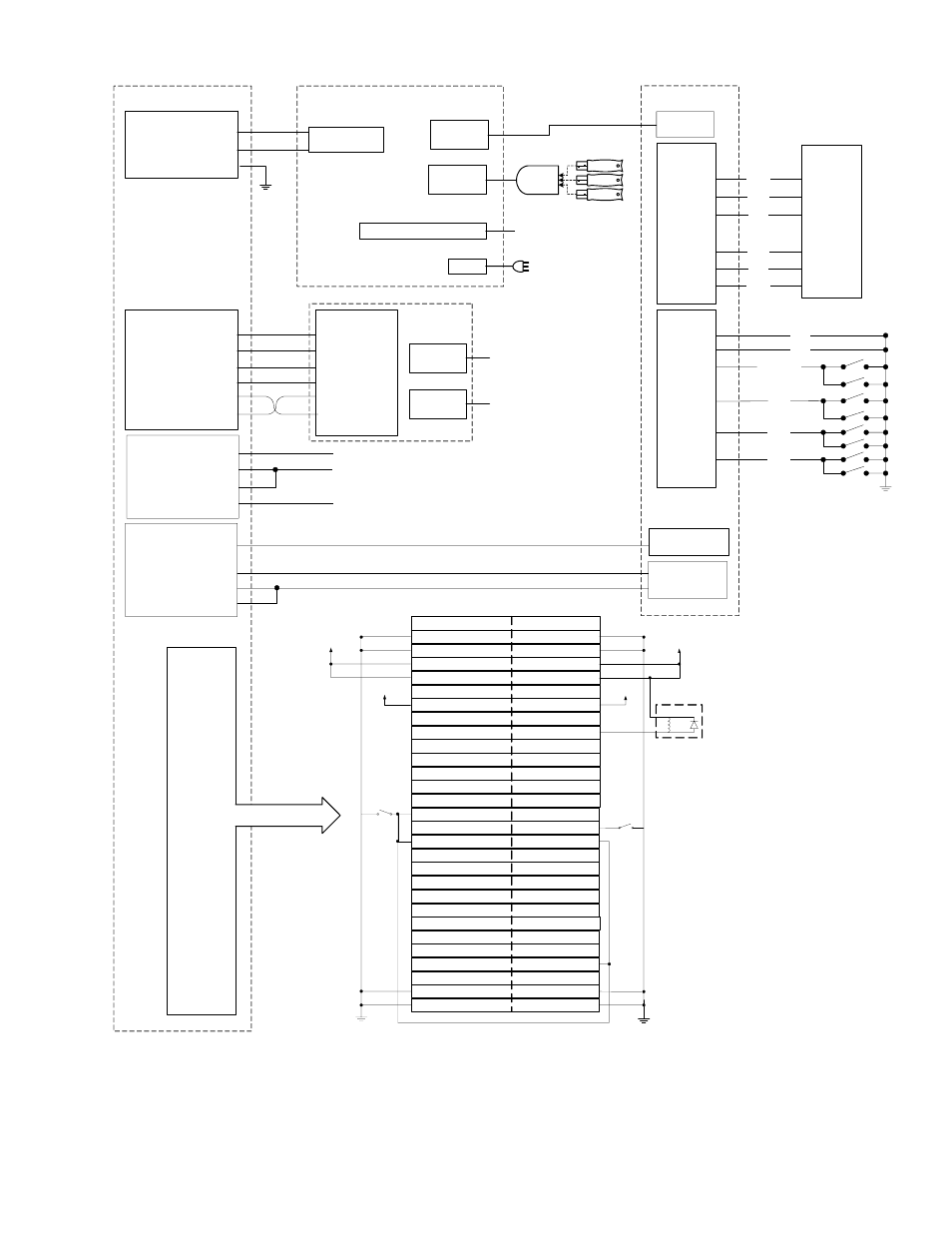
Figure 6. detailed wiring diagram – Atari 040-0050-01 User Manual
Page 44
Section 8 – Diagrams and Schematics
gvrSX™ Conversion System Manual
Page 44 of 48
040-0050-01
Rev. A 10/29/2004
Jamma Conversion Board
J4 (Video In)
Video Green 2
Video Blue 3
Video Red 1
Video Sync 4
Video GND 6
J7
1 Video Red
2 Video Green
3 Video Blue
4 Video GND
6 Hsync/
UVC
J1
VGA In
To VGA Out
on Computer
J8
Power In
To DC Power
Supply
Computer
Composite
NC 5
5 Video Sync
VGA Port on Video Card
AC In
USB Port
To Power
Strip
To Monitor
or UVC
Happ UGCI Board
VCC 1
GND 5
GND 6
YAX 9
XAX 10
VCC 12
J6
GND 1
GND 2
J54 4
J53 5
J52 6
J51 7
J4
BLK
BLK
RED-BLK
GRY
WHT
GRN
Trigger A*
Trigger B*
Missiles
Cannon
ORG
BRN
BRN
BLU
PPL
ORG
Joystick
* Trigger buttons are
located on joystick.
Jamma Connector
Ground
A (29)
1
Ground
Ground
B (30)
2
Ground
+5V
C (31)
3
+5V
E (33)
5
+5V
D (32)
4
+5V
+12V
F (34)
6
+12V
H (35)
7
J (36)
8
Coin Counter Out Amp
Left Speaker -
3
L (38)
10
Left Speaker +
3
K (37)
9
Right Speaker -
3
M (39)
11
Right Speaker +
3
Video Green
1
N (40)
12
Video Red
1
Video Sync
1
P (41)
13
Video Blue
1
S (43)
15
Operator Button
Coin Switch
R (42)
14
Video Ground
Coin 2
T (44)
16
Coin 1
U (45)
17
Start Button
2
V (46)
18
X (48)
20
W (47)
19
Y (49)
21
Z (50)
22
a (51)
23
c (53)
25
Coin 3
b (52)
24
d (54)
26
Ground
f (56)
28
Ground
Ground
e (55)
27
Ground
Solder Side
Parts Side
Notes:
1
Jamma video connections are not used with the Wells -Gardner
®
monitor upgrade.
2
Jamma button connectors are not used if the buttons are connected directly to J6 on the Jamma Conversion Board.
3
For mono audio, only the Left Speaker + and Left Speaker - speaker connections are used.
Power is supplied to the Jamma Harness through JI on the Jamma Conversion Board.
Coin Counter
Coin Switch
To +5 VDC
Devices
To +12 VDC
Devices
To +5 VDC
Devices
To +12 VDC
Devices
+
-
USB Port
USB Port
J2 (Audio In)
R Audio 2
L Audio 5
GND 1
Speakers Out
Jamma
Edge
To Jamma
Connector
USB
Hub
Dongle
Dongle
Dongle
J1 (PWR)
GND 2
GND 3
+12 VDC 1
+5 VDC 4
To DC Power Supply
J7 (Aux Coin/Test)
GND 4
Meter Drive Input 3
Test 2
Coin 1
J3
J5
8 GND
1 CN1
2 JS6
Figure 6. Detailed Wiring Diagram