4 functions of dipswitches – RMS Technologies IMD23 W/ POLE DAMPING TECHNOLOGY User Manual
Page 7
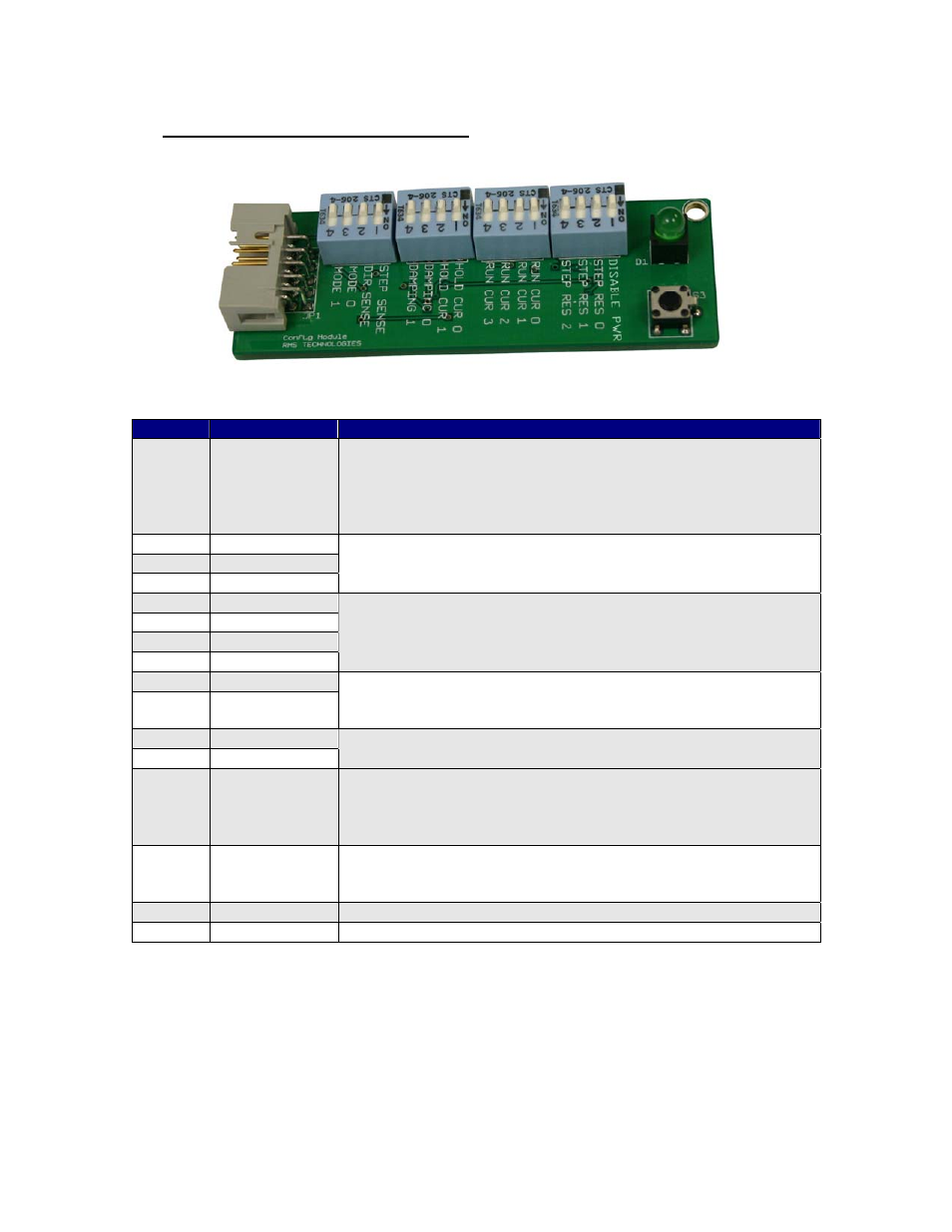
Configuration Module (ACC-02)
Page 7
Version 1.00
8/31/2007
4 Functions of Dipswitches
Switch Abbreviation Description of Function
SW1-1 Disable PWR
Disable Power
On: Motor powers off when disabling unit and step is
inhibited
Off: Motor receives current from the last step pulse input
prior to disabling the unit and step is inhibited.
SW1-2 Step Res 0
SW1-3 Step Res 1
SW1-4 Step Res 2
Step Resolution:
A combination of these three dipswitches sets the step
resolution from half step to 256x microstepping.
SW2-1 Run Cur 0
SW2-2 Run Cur 1
SW2-3 Run Cur 2
SW2-4 Run Cur 3
Run Current:
A combination of these four dipswitches sets the run
current from 0.2 Amps to 3.0 Amps Peak current.
SW3-1 Hold Cur 0
SW3-2 Hold Cur 1
Holding Current: A combination of these two dipswitches
sets a percentage of the run current as holding current:
0%, 25%, 50%, 100%
SW3-3 Damping 0
SW3-4 Damping 1
Damping Modes: A combination of these two dipswitches
sets four different damping modes for smoother operation.
SW4-1 Step Sense
Step Sense: Step pulses entered into the driver can be
read on the rising or falling edge of the pulse. On: reads
on the positive or rising edge. Off: reads on the negative
or falling edge.
SW4-2 Dir Sense
Direction Sense: Changes direction upon seeing a rising
edge (dipswitch ON) or seeing a falling edge (dipswitch
OFF)
SW4-3 Mode 0
Not activated
SW4-4 Mode 1
Not activated
*Note: Dipswitches are switched “ON” when switches are towards the RIGHT when
looking at the configuration module and reading the silk screen descriptions upright.
There is also a marking labeled as “ON”.