Comfort-Aire VFH 24 CA User Manual
Page 15
Heat Controller
VFH InverterFlex
®
- Ceiling Cassette
13
5.
As the panel is being screwed in, ensure that it remains level on all sides.
6.
The insulation material of the ceiling cassette panel will compress to create a tight seal.
7.
Once installed, the inlet grille can be re-attached to the frame. The shipping screws on the tabs do not
need to be re-installed.
24K Cassette Panel Installation:
ATTENTION:
•
Before carrying out the panel installation process, please refer to the Electrical Panel Connections
section of the manual. The 24K requires a pin connector to be connected to CN21 on the indoor
unit’s control board under the control panel cover. This step is easiest if done before the 24K panel
is installed.
•
The 24K panel should be aligned such that the louver motor is on the same corner as the indoor
unit’s refrigerant connections.
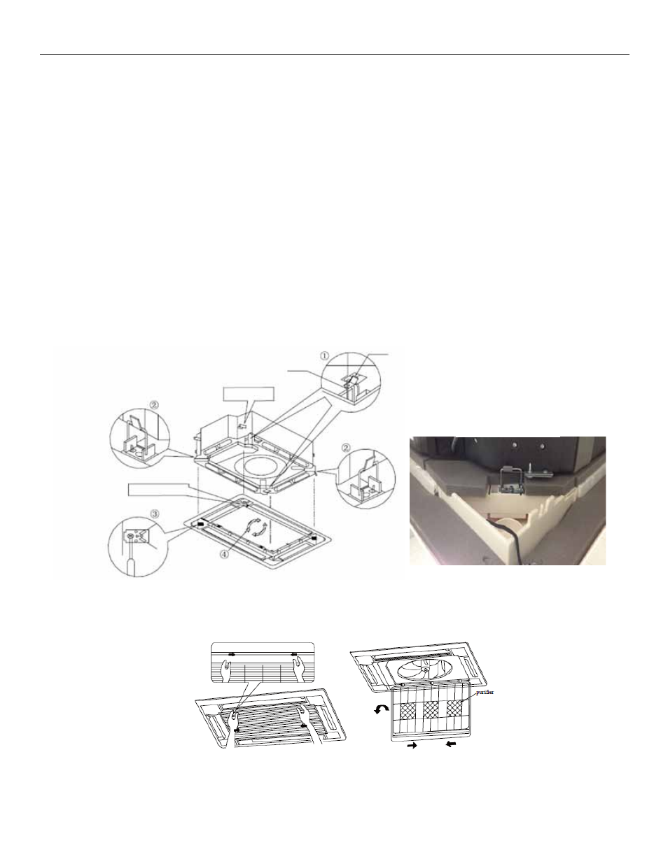
1.
24K panel should be suspended by the metal clips onto the indoor unit’s hooks during installation.
2.
Two of the hooks for the metal clips are on the exterior edge of the unit; the other two can only be
accessed when the air inlet grille is removed, by reaching inward.
3.
To remove the air inlet grille, unscrew the (2) small shipping screws on the tabs of the air inlet grille,
then push the tabs in to open the inlet grille.
4.
The inlet grille can then be removed from the panel frame to access the metal clips and attach to the
inside of the unit.
5.
Once all Four clips are attached the hooks on the unit, the panel needs to be tightened. To access the
screws for tightening down, each corner cover must be removed.
Photo of clip
attached to hook
Latch
Hook
Louver Motor
Refrigerant
Connections