Wired wall thermostat installation – Comfort-Aire VFH 24 CA User Manual
Page 14
VFH InverterFlex
®
- Ceiling Cassette
Heat Controller
12
Wired Wall Thermostat Installation:
The ceiling cassette comes with an optional wall mounted wired thermostat.
ATTENTION:
•
Use of the wall mounted thermostat will disable both the unit’s control panel and the wireless
remote. Alternatively, if the wall mounted thermostat is disconnected; both the unit’s control panel
and wireless remote can be used to operate the unit.
•
Each ceiling cassette must use an independent wireless remote or wall mounted wired thermostat.
•
The wired thermostats cannot be daisy chained together nor can one wireless remote control be
programmed to operate all of the ceiling cassettes installed on a system.
•
If the wired thermostat is plugged in, the control panel of the unit will
1.
Installation of the optional wired thermostat requires a connection to be made between it and the
indoor unit’s control board.
2.
Pass one end of the thermostat cable through the rubber gasket on the rear of the wall mounted
thermostat and connect the connector to the board.
3.
Run the opposite end of the thermostat wire through the rubber gasket of the indoor unit’s electrical
control box.
4.
Remove the indoor unit’s electrical box cover and connect the thermostat wire’s connector to the
connector labeled CN9 on the board.
5.
Re-install the electrical box cover and mount the thermostat to the wall location, if not already done.
6.
Any additional slack in the thermostat wire can be coiled up and bound with the provided wire ties.
NOTE: Refer to the owner’s manual for instructions regarding the operation of the wired thermostat.
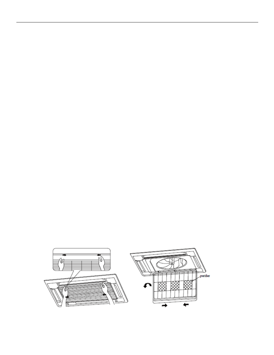
Cassette Panel Installation:
12/18K Cassette Panel Installation:
ATTENTION: The 12K/18K panel should be aligned so that its control panel is located on the same side as the
indoor unit’s electrical box.
1.
The screw holes for the 12K/18K unit cannot be accessed without removing the air inlet grille that
houses the filter.
2.
To remove it, unscrew the (2) small shipping screws on the tabs of the air inlet grille, then push the tabs
in to open the inlet grille.
3.
The inlet grille can then be removed from the panel frame to expose the screw holes to attach it to the
indoor unit.
4.
The screws provided with a washer and lock washer should be used to attach the panel frame to the
indoor unit. Attention: Before screwing in the panel to the indoor unit, be certain that all of the
connecting cables are pulled out for access later.