Ariens Sno-Thro 920001- ST624E User Manual
Page 22
GB - 22
To adjust traction clutch (Figure 32):
1. With the traction drive clutch lever disengaged,
loosen the jam nut on the cable adjuster.
Turn adjustment barrel up the cable to decrease
the distance between clutch lever and handlebar.
Turn the adjustment barrel down the cable to
increase the distance between clutch lever and
handlebar.
2. Check traction clutch lever distance and repeat
adjustment steps if necessary.
3. Tighten jam nut on traction cable adjustment
barrel.
4. With the clutch disengaged, check that there is
more than 1/32 in. (0.8 mm) clearance between
friction disc and drive plate assembly. See on
page 22
FRICTION DISC REPLACEMENT
Remove Friction Disc (Figure 33):
1. Shut off engine, remove key, disconnect spark
plug wire and allow unit to cool completely.
2. Place the unit into the service position on a level
surface.
3. Remove lockpins from wheel axles and remove
wheels.
4. Remove bottom cover by removing six hex bolts.
5. Disconnect pivot pin from the speed selector arm.
Save the hardware for reinstallation.
6. Remove spring clip pin nearest drive gear from
hex shaft.
7. Remove left bearing flange from frame.
8. Slide hex shaft to the left to remove the flat
washer, pinion gear and friction disc assembly
from the hex shaft.
NOTE: Be sure to save washers between bearing and
sliding fork for reassembly.
9. Remove friction disc assembly from frame.
10. Remove three screws holding friction disc to
carrier bearing.
11. Remove old friction disc. Put the new friction disc
in place, cup side to carrier bearing.
12. Reinstall three screws into new friction disc and
carrier bearing. Torque to 5 – 6 lbf-ft. (6.8 – 8.13
N•m).
CAUTION: Before tipping unit, remove
enough fuel so that no spills occur.
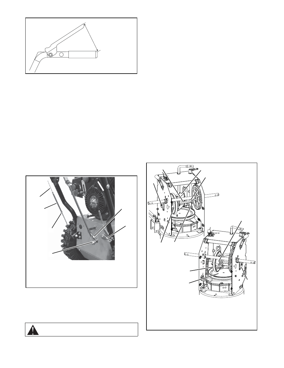
Traction Clutch Lever
OS2490
Figure 31
7-1/2 – 8 in.
(19.0 – 20.3 cm)
Figure 32
1. Traction Drive Clutch
Cable
2. Adjustment Barrel
3. Jam Nut
4. Adjustment Pivot Pin
5. Speed Selector Arm
6. Attachment Clutch Arm
OS8094
1
4
5
6
1. Hex Shaft
2. Friction Disc Assembly
3. Left Bearing Flange
4. Speed Selector Arm
5. Friction Disc
6. Right Bearing Flange
7. Carrier Bearing
8. Spring Clip
9. Drive Gear
10.Drive Plate Assembly
OS8095
Figure 33