Ariens Sno-Thro 920001- ST624E User Manual
Page 12
GB - 12
Scraper Blade
The scraper blade allows the back of the housing to
keep better contact with the surface being cleared. It
also prevents damage to the housing from normal
wear.
IMPORTANT: DO NOT allow Scraper Blade to wear
too far or Auger/Impeller housing will become
damaged.
Runners
The runners control the distance between the scraper
blade and the ground. Adjust runners equally to keep
blade level with the ground. Refer to Pre-Start on
page 12 for recommended settings.
FILLING FUEL TANK
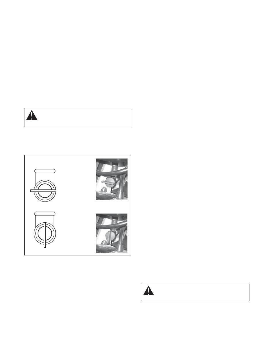
Fuel Shut-Off Valve
IMPORTANT: The fuel shut-off valve MUST be in the
closed position prior to transporting the unit.
The fuel shut-off valve has two positions:
To add fuel to fuel tank:
1. ALWAYS place unit in open or well-ventilated
area.
2. Stop engine and allow to cool.
3. Clean Fuel Cap and surrounding area to prevent
dirt from entering Fuel Tank.
4. Remove Cap.
IMPORTANT: DO NOT use gasohol or gasoline
containing alcohol. See Engine Manual for correct type
and grade of fuel.
5. Fill fuel tank to within 1/2 in. (1.2 cm) below
bottom of filler neck with unleaded gasoline.
NOTE: Tank capacity is 3.5 qt (3.3 L)
6. Replace Fuel Cap and tighten.
7. ALWAYS clean up any spilled fuel.
PRE-START
1. Frozen Impeller
IMPORTANT: Before starting engine, check impeller to
be sure it is not frozen.
To check impeller:
1. With ignition key switch in “Stop” position,
squeeze Attachment Clutch Lever to Engaged
position.
2. Pull Recoil Starter Handle.
3. If Impeller is frozen, (cannot pull Starter Handle)
move unit to a heated area and thaw to prevent
possible damage.
2. Check Function of Clutches
If clutches do not engage or disengage properly, adjust
or repair before operation. See Attachment
Clutch/Brake Adjustment on page 19 and Traction
Drive Clutch Adjustment on page 21
3. Check Dual Handle Interlock
Without the engine running, press down (engage) both
clutch levers. Release attachment clutch lever.
Attachment clutch should remain engaged until traction
clutch lever is released, then both clutches must
disengage.
If clutches do not engage or disengage properly, adjust
or repair before operation (see Attachment
Clutch/Brake Adjustment on page 19 and Traction
Drive Clutch Adjustment on page 21).
4. Check Axle Lock
Use the axle lock pins to lock or unlock the wheels.
Lock both wheels to increase traction; unlock one
wheel to allow for easier turning of the unit.
5. Check Runners
Check and adjust Runners (Runners on page 16).
Allow 1/8 in. (3 mm) between scraper blade and hard,
smooth surface(s). Allow 1-1/4 in. (30 mm) between
scraper blade and uneven or gravel surfaces.
6. Check Engine Fuel & Crankcase Oil
Check and add fuel if required. Check that the engine
crankcase oil is full using dipstick. Refer to Engine
Manual for detailed instructions.
WARNING: AVOID INJURY. Read and
understand the entire Safety section before
proceeding.
Figure 10
Open Position: Use
this position to run
the unit.
Closed Position:
Use this position
to service,
transport, or store
the unit.
OS7117
WARNING: AVOID INJURY. Read and
understand the entire Safety section before
proceeding.