Ariens Sno-Thro 920001- ST624E User Manual
Page 21
GB - 21
Check Attachment Brake (Figure 29)
1. With the clutch lever disengaged, brake pad must
contact attachment belt. With clutch lever
engaged, brake pad must be more than 1/16 in.
(1.6 mm) from belt. If there is more than 1/16 in.
(1.6 mm) gap, go to Check Belt Finger Clearance
(Figure 30) on page 21. If there is less than 1/16
in. (1.6 mm) gap, go to Step 2.
2. If there is less than 1/16 in. (1.6 mm) gap
between brake pad and belt, follow these steps:
a. To increase brake pad gap, loosen idler
adjustment nut, and move idler away from
belt. Position idler to achieve a 1/16 in. (1.6
mm) minimum brake pad gap and a 1/2 – 7/8
in. (12.7 – 22.2 mm) gap between the plastic
roller and the frame.
b. Check the clutch cable spring extension and
adjust as necessary to achieve a 1/2 – 9/16
in. (12.7 – 14.3 mm) spring extension.
c. If the cable needed adjustment, recheck gaps
described in step 1. Repeat steps as
necessary until brake clearance, roller gap
and spring extension are within specified
ranges.
IMPORTANT: If adjustments cannot be brought into
specified ranges see your Dealer for repairs.
Check Belt Finger Clearance (Figure 30)
1. With clutch lever engaged, the belt finger located
opposite the belt idler must be less than 1/8 in. (3
mm) from belt, but not touching the belt.
To adjust belt finger, loosen the bolts and move
the finger to the proper position. Tighten the bolts
and recheck the belt finger clearance.
2. Replace the belt cover.
TRACTION DRIVE CLUTCH ADJUSTMENT
If drive slips, adjust traction clutch to compensate for
friction disc wear.
To test traction clutch (Figure 31):
1. Put unit in first forward speed.
2. Without engine running, push unit forward while
slowly moving the traction drive clutch lever
toward the handlebar.
3. Measure distance between lever and handlebar
when the wheels begin to brake. If distance is not
7-1/2 – 8 in. (19.0 – 20.3 cm), adjust the traction
clutch.
Figure 28
OS8090
1. Engine Sheave
2. Traction Drive Belt
3. Traction Belt Idler
4. Attachment Idler Nut
5. Attachment Belt Idler
6. Belt Finger
7. Traction Belt Idler Nut
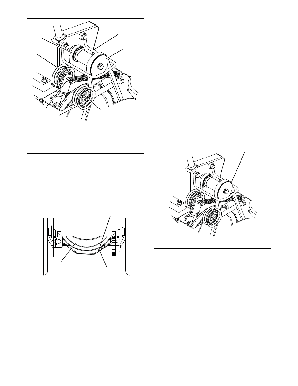
Figure 29
OS8092
Minimum of 1/16 in. (1.6 mm)
1. Brake Arm and Pad
2. Attachment Pulley
Figure 30
OS8067
Check belt finger clearance here. With the
attachment clutch engaged, there should be
less than 1/8 in. (3 mm) clearance between the
belt and the belt finger. The belt finger should
not touch the belt.