Rugged Ridge 4-Inch Lift Kit with Shocks, 07-14 Jeep Wrangler (JK) User Manual
Page 3
Pg 3
8. Locate the factory front track bar mount. Place the new Rugged Ridge
relocation bracket inside the factory mount. Drill out the outer factory holes
all the way through the rearward plate using a 7/16" drill bit. (See Photo
#6) NOTE: It is recommended at this time to put a re-enforced weld on
the factory bracket. Attach the bracket at the outer two locations using the
7/16 x 2 1/2" fine thread bolts, washers and nuts. Attach bracket at the
factory location using the factory bolt. Let the weight of the frame down on
to the new coils. Attach track bar to new bracket using the 14x80mm bolt,
washers and nut.
9. Re-Attach front drive shaft. Assemble new Sway bar end links using the
5/8" Hourglass bushings and steel sleeves. Attach eyes using the 1/4"
snap pins. Attach end link to the axle using the factory hardware. (See
Photo #7) Attach the lower portion of the sway bar using the 1/2 x 2 1/2"
button head bolt. Use one large USS washer under the nut. Re-Attach
front Drive Shaft.
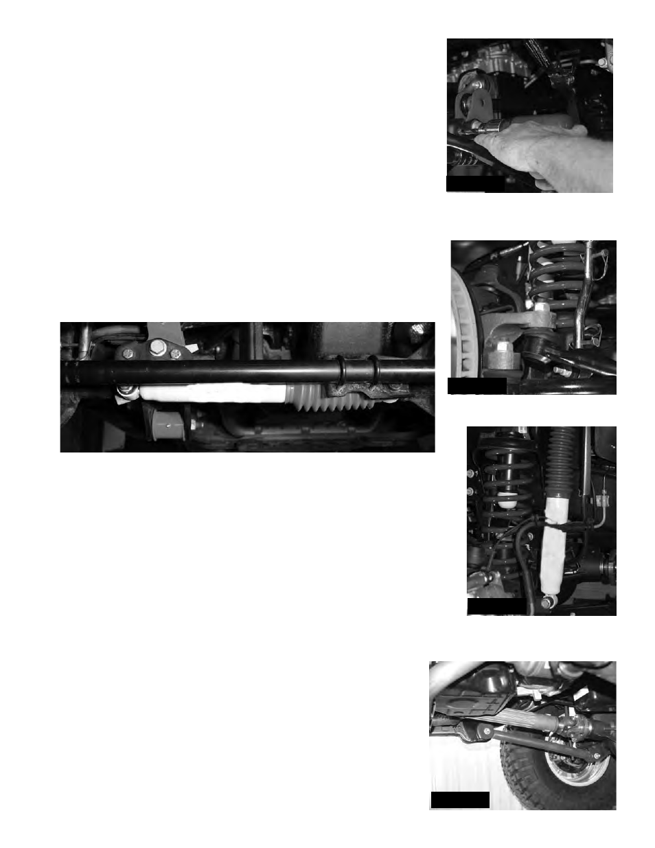
If installing Rugged Ridge Steering Stabilizer, install at this time. (See
Photo Below)
.
10. Install new Front shocks using hardware supplied. (See Photo #8).
Locate new Lower front control arms. Install bushings and sleeves. Install
3/16" Tap in grease fittings into each end of the control arm. Note: The rear
of the control arms have 2 locations for grease fittings. Therefore there
is not a left or right control arm. When installed, one grease fitting will be
accessible from the bottom. Install arms so that off set bend is toward the
inside of the vehicle. Install using factory hardware. (See Photo #9)
11.
Install tires and wheels. Lower vehicle to the ground.
Note: Most models come equipped with a front transmission
cross member. This cross member has 3 attachment points. One
at each frame rail and one at the rear cross member. It will be
necessary to lower this cross member using the supplied 1"
spacers for driveline clearance. Install spacers using the 12 x
65 mm bolts supplied.
Photo #6
Photo #7
Photo #8
Photo #9