Installation instructions, Prior to doing this run a tape – Rugged Ridge HD Tie Rod & Drag Link Kit, 87-95 Jeep Wrangler (YJ) User Manual
Page 2
Installation Instructions:
(1) (ALL) Properly secure vehicle. Place in gear or park and set emergency brake. For further
safety block tires.
(2) (TJ-XJ-ZJ) Remove old steering linkage. DO NOT alter the position of the front wheels or
steering wheel during the removal. Keeping these components in the original position will
allow you to keep your front end alignment as close to original as possible. Prior to
installation run a tape measurer from passenger side knuckle (inner) to Driver’s side
knuckle (inner) and note length. If knuckles are moved by accident you will be able to return
to the correct position by using this measurement. After any steering modification an
alignment by a professional shop is recommended.
(YJ 87-95) Remove old steering linkage. It may be necessary to move one wheel – knuckle
outbound to remove original steering linkage.
Prior to doing this run a tape
measurer from passenger side knuckle (inner) to Driver’s side knuckle
(inner) and note length
. You will need this measurement to return your steering to its
original position. After any steering modification an alignment by a professional shop is
recommended.
(3) (TJ-XJ-ZJ) Attach H/D Cross-Over steering as shown below (Fig.2A). The dual attachment
point tie-rod end (18043.27) should be mounted to the passenger side knuckle. With tubes
and tie-rod ends installed turn all keeper nuts full out (Fig.3). By turning the H/D center
tubes clock wise or counter clockwise adjustments to the lengths can be made. Adjust until
all mounting holes are aligned. Attach castle nuts and torque to 60ft-lbs for all locations.
During adjustments it is important to keep the front wheels and pitman arm in the original
position.
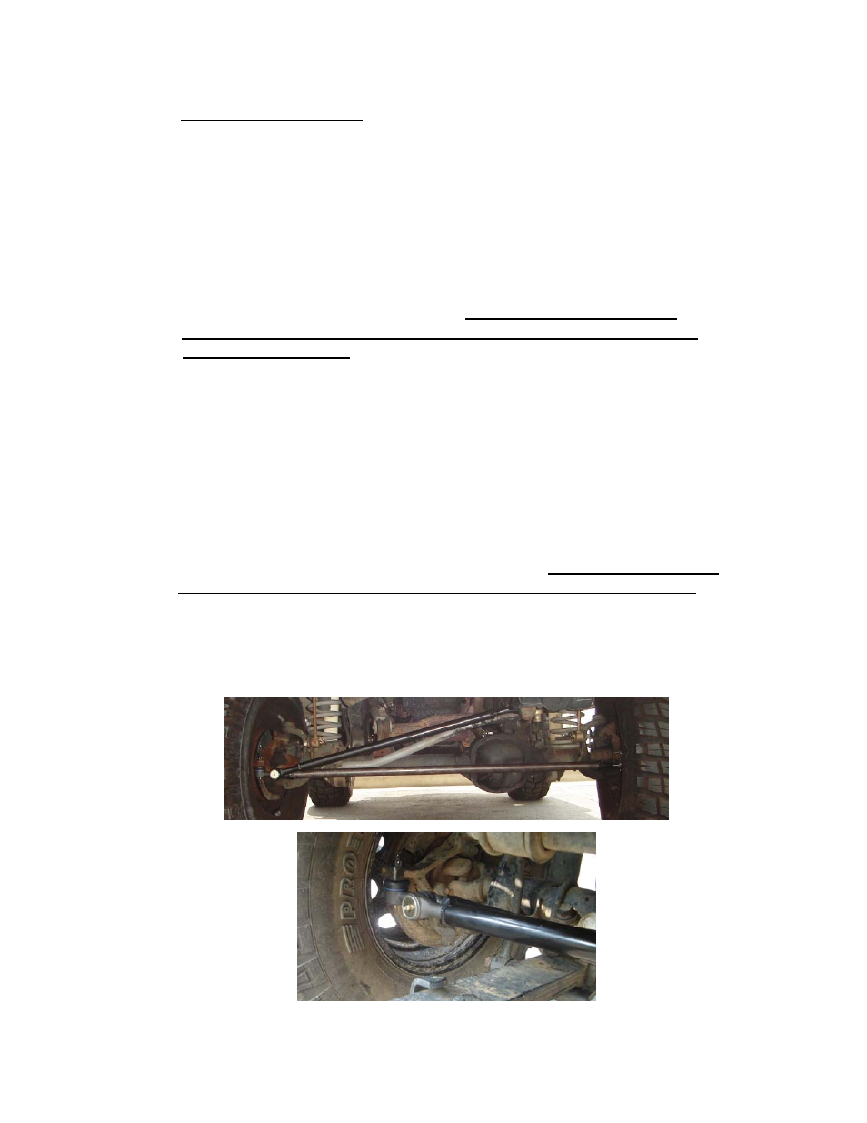
(YJ 87-95) Insert the new H/D Cross-Over steering. Start at the knuckle that has been
moved outbound and slide over leaf springs (Fig.2B). The dual attachment point tie-rod end
(18043.28) should be mounted to the passenger side knuckle.
Using the measurement
taken in step 2 return the wheel & knuckle back to the correct position.
With
tubes and tie-rod ends installed into knuckles and pitman arm turn all keeper nuts full out
(Fig.3). Adjustments to lengths are made by turning the H/D center tubes clock wise or
counter clockwise. Adjust until all mounting holes are aligned. Attach castle nuts and torque
to 60ft-lbs for all locations. During adjustments it is important to keep the front wheels and
pitman arm in the original position.
Fig.2A
Fig.2B
Page 2