Hardware setup – Asus A7M266-D User Manual
Page 36
36
ASUS A7M266-D User’s Manual
Connectors
3. H/W SETUP
3. HARDWARE SETUP
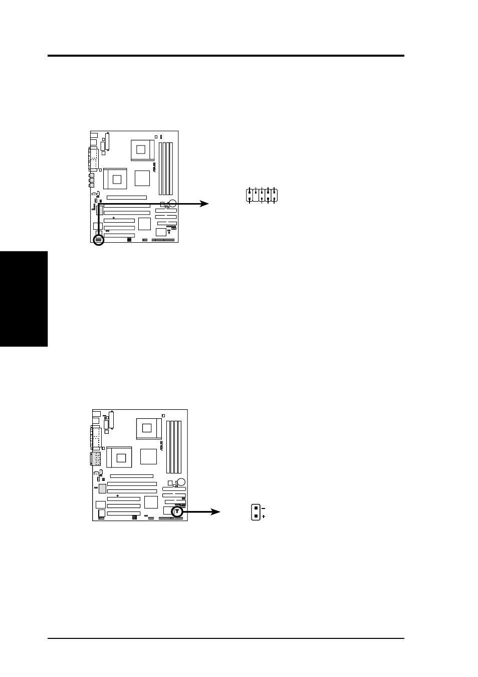
17) IDE Activity LED (2-pin IDELED)
This connector supplies power to the cabinet’s IDE activity LED. Read and
write activity by devices connected to the Primary/Secondary IDE connectors
will cause the LED to light up.
A7M266-D
®
A7M266-D Intel Panel Connector
IAPANEL
Backpanel_LineOut_R
LineOut_L
AGND_A
Backpanel_LineOut_L
LineOut_R
+5V
A
MICPWR
MIC2
NC
1
2
9
10
(Key)
16) Front Panel Audio Connector (10-1 pin IAPANEL)
Attach the Front Panel audio cable to the IAPANEL connector for audio control.
NOTE: The motherboard ships with Jumper caps over pins 1-2 and 5-6.
Remove them only when making connections to a Front Panel.
®
A7M266-D
A7M266-D IDE Activity LED
TIP: If the case-mounted LED does not
light, try reversing the 2-pin plug.
IDELED
- Xonar DX (80 pages)
- Xonar DX (10 pages)
- PCI Express Audio Card Xonar DX (70 pages)
- Xonar D2X (84 pages)
- D2X (88 pages)
- Audio Card Xonar D2X (70 pages)
- Xonar D2X (88 pages)
- ROG Xonar Phoebus (72 pages)
- ROG Xonar Phoebus (122 pages)
- Xonar DSX (29 pages)
- Xonar DSX (26 pages)
- Xonar DGX (33 pages)
- Xonar DGX (58 pages)
- Xonar DGX (38 pages)
- Xonar DG (28 pages)
- Xonar DG (54 pages)
- Xonar DG (58 pages)
- Xonar DG (32 pages)
- Xonar Essence ST (52 pages)
- Xonar Essence ST (35 pages)
- Xonar Essence ST (40 pages)
- Xonar Essence ST (53 pages)
- Xonar DS (33 pages)
- Xonar DS (54 pages)
- Xonar Xense (45 pages)
- Xonar Xense (47 pages)
- Xonar Xense (70 pages)
- Xonar U3 (56 pages)
- Xonar U3 (38 pages)
- Xonar Essence STX (10 pages)
- Xonar Essence STX (32 pages)
- Xonar Essence STX (49 pages)
- XONAR D1 E4009 (72 pages)
- Xonar D1 (72 pages)
- Xonar D1 (80 pages)
- Xonar D1 (10 pages)
- Xonar Essence One (7 pages)
- Xonar Essence One (5 pages)
- Xonar HDAV 1.3 (100 pages)
- Motherboard M4A78-EM (64 pages)
- A7N8X-VM/400 (64 pages)
- K8V-XE (20 pages)
- K8V-XE (86 pages)
- M2R32-MVP (60 pages)
- M2R32-MVP (160 pages)