Hardware setup, Connectors 3. h/w setup – Asus A7M266-D User Manual
Page 35
ASUS A7M266-D User’s Manual
35
3. HARDWARE SETUP
Connectors
3. H/W SETUP
®
A7M266-D
A7M266-D True-Level Line Out Header
1
HPHONE
HP
OUT
L
T
GND
HP
OUT
R
T
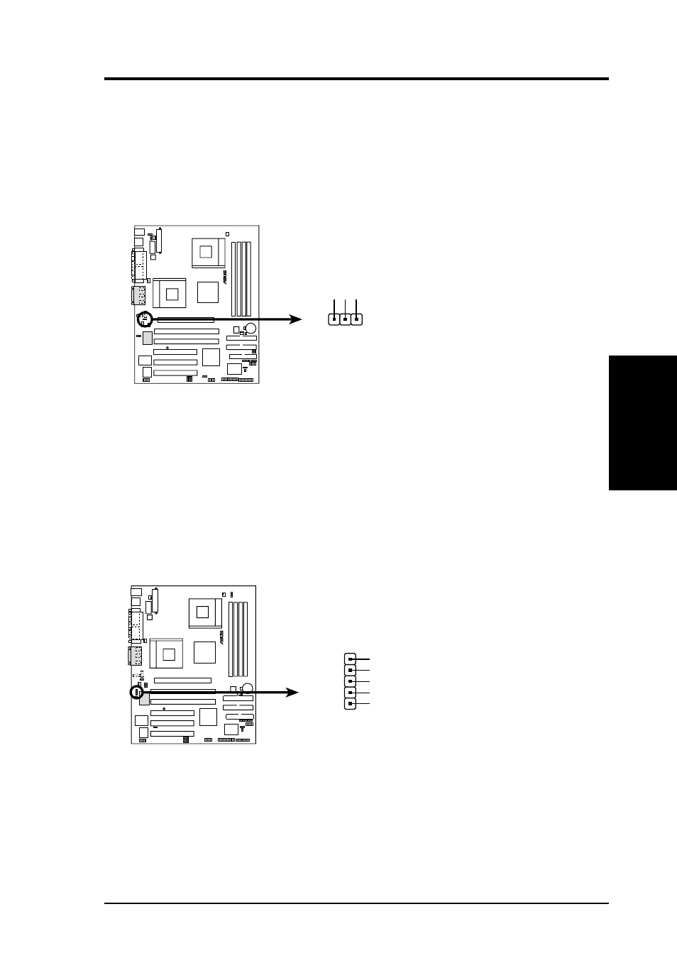
14) Headphone True-level Line Out Header (3-pin HPHONE) (optional)
This connector supports the chassis-mounted headphone instead of connecting
an external headphone to the rear panel connector.
NOTE: The internal microphone does not work if there is an external mi-
crophone connected to the external Mic (pink) jack. You may only use one
microphone at a time.
15) Audio Input Line In Header (5-pin LINE_IN) (optional)
This connector suports audio input on left and right stereo audio channels.
NOTE: The motherboard ships with Jumper caps over pins 1-2 and 4-5.
Remove them only when making audio input connections.
A7M266-D
®
A7M266-D LINE_IN Connector
LINE_IN
AGND_A
Backpanel_LineIn_R
LineIN_R
LineIN_L
Backpanel_LineIn_L
1
- Xonar DX (80 pages)
- Xonar DX (10 pages)
- PCI Express Audio Card Xonar DX (70 pages)
- Audio Card Xonar D2X (70 pages)
- Xonar D2X (88 pages)
- Xonar D2X (84 pages)
- D2X (88 pages)
- ROG Xonar Phoebus (72 pages)
- ROG Xonar Phoebus (122 pages)
- Xonar DSX (26 pages)
- Xonar DSX (29 pages)
- Xonar DGX (38 pages)
- Xonar DGX (33 pages)
- Xonar DGX (58 pages)
- Xonar DG (54 pages)
- Xonar DG (58 pages)
- Xonar DG (32 pages)
- Xonar DG (28 pages)
- Xonar Essence ST (35 pages)
- Xonar Essence ST (40 pages)
- Xonar Essence ST (53 pages)
- Xonar Essence ST (52 pages)
- Xonar DS (54 pages)
- Xonar DS (33 pages)
- Xonar Xense (70 pages)
- Xonar Xense (45 pages)
- Xonar Xense (47 pages)
- Xonar U3 (56 pages)
- Xonar U3 (38 pages)
- Xonar Essence STX (49 pages)
- Xonar Essence STX (10 pages)
- Xonar Essence STX (32 pages)
- XONAR D1 E4009 (72 pages)
- Xonar D1 (72 pages)
- Xonar D1 (80 pages)
- Xonar D1 (10 pages)
- Xonar Essence One (7 pages)
- Xonar Essence One (5 pages)
- Xonar HDAV 1.3 (100 pages)
- Motherboard M4A78-EM (64 pages)
- A7N8X-VM/400 (64 pages)
- K8V-XE (86 pages)
- K8V-XE (20 pages)
- M2R32-MVP (60 pages)
- M2R32-MVP (160 pages)