Post-assembly checks, Assembly references, Bolt torque values – Goulds Pumps HT 3196 i-FRAME - IOM User Manual
Page 119: Ost-assembly checks
Post-assembly checks
Perform these checks after you assemble the pump, then continue with pump startup:
• Rotate the shaft by hand in order to make sure that it rotates easily and smoothly and that there is no
rubbing.
• Open the isolation valves and check the pump for leaks.
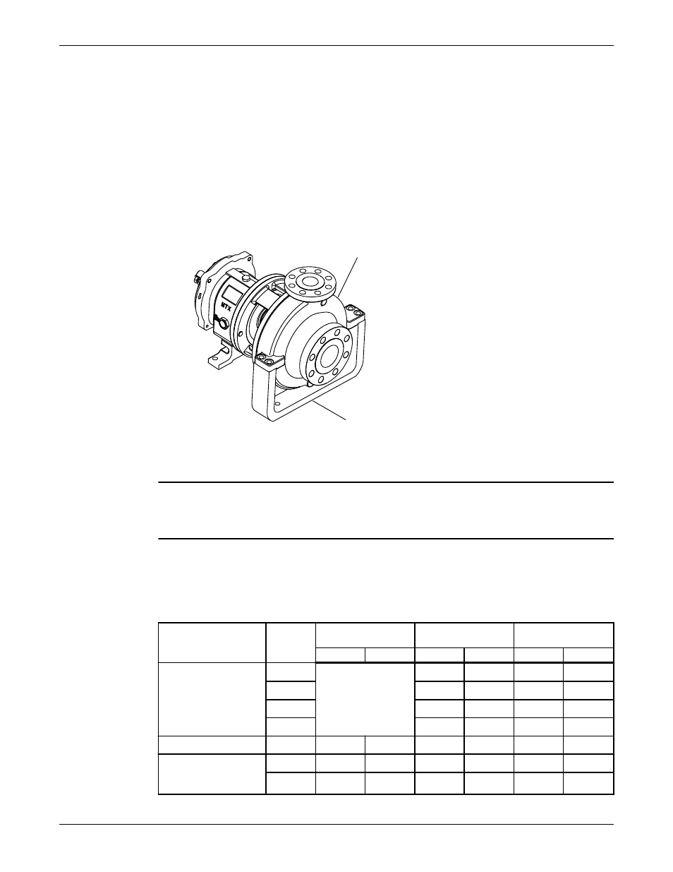
Reinstall the back pull-out assembly for the HT 3196
1. Attach the casing support (239) to the casing (100).
The stamped part number on the casing support is located on the left side when you face the casing
suction.
100
239
2. Reinstall the coupling guard.
Refer to the Install the coupling guard section for more information.
NOTICE:
Risk of damage to the mechanical seal or shaft sleeve on units supplied with cartridge mechanical seals.
Prior to startup, make sure to tighten the set screws in the seal locking ring and remove the centering clips.
Assembly references
Bolt torque values
This table provides the bolt torque values.
Table 17: Bolt torque, lb-ft (Nm)
Location
Frame
3196, CV 3196, LF
3196, 3796
NM 3196
3198
Lube
Dry
Lube
Dry
Lube
Dry
Casing bolts (370) or
casing nuts (425)
6-in. STi
Refer to the
maximum torque
values in lb-ft (Nm)
for casing bolts table.
27 (36)
40 (53)
N/A
N/A
8-in. STi
20 (27)
30 (40)
35 (47)
53 (71)
MTi, LTi
27 (36)
40 (53)
35 (47)
53 (71)
XLT-i, i17
N/A
N/A
N/A
N/A
Frame-to-adapter bolts All
20 (27)
30 (40)
20 (27)
30 (40)
20 (27)
30 (40)
Bearing-clamp ring
bolts (236A) - duplex
bearing only
STi, MTi 10* (1.1)
17* (1.9)
10* (1.1)
17* (1.9)
10* (1.1)
17* (1.9)
LTi
55* (6.2)
83* (9.4)
55* (6.2)
83* (9.4)
55* (6.2)
83* (9.4)
Maintenance
Model HT 3196 i-FRAME Installation, Operation, and Maintenance Manual
117