Pump-to-driver alignment instructions – Goulds Pumps 3355 - IOM User Manual
Page 20
Installation
b) Attach the other indicator (A) so that the indicator rod comes into contact with the inner
end of the driver coupling half.
This indicator is used to measure angular misalignment.
2. Rotate the pump coupling half (X) in order to check that the indicators are in contact with
the driver coupling half (Y) but do not bottom out.
3. Adjust the indicators if necessary.
Pump-to-driver alignment instructions
Perform angular alignment for a vertical correction
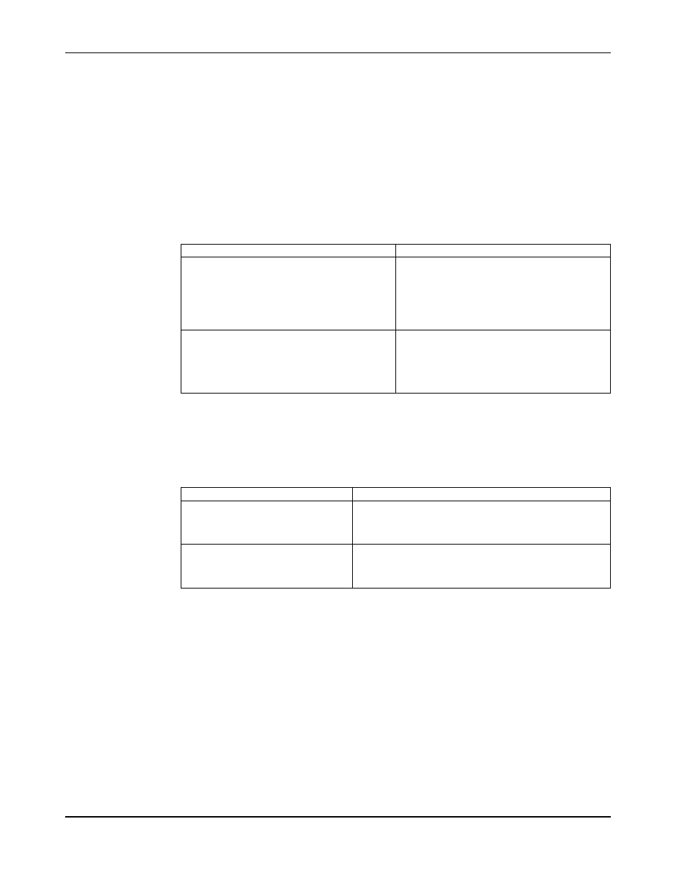
1. Set the angular alignment indicator to zero at the top-center position (12 o’clock) of the
driver coupling half (Y).
2. Rotate the indicator to the bottom-center position (6 o’clock).
3. Record the indicator reading.
When the reading value is...
Then...
Negative
The coupling halves are farther apart at the
bottom than at the top. Perform one of these
steps:
• Add shims in order to raise the feet of the
driver at the shaft end.
• Remove shims in order to lower the feet of the
driver at the other end.
Positive
The coupling halves are closer at the bottom than
at the top. Perform one of these steps:
• Remove shims in order to lower the feet of the
driver at the shaft end.
• Add shims in order to raise the feet of the
driver at the other end.
Perform angular alignment for a horizontal correction
1. Set the angular alignment indicator (A) to zero on left side of the driver coupling half (Y),
90° from the top-center position (9 o’clock).
2. Rotate the indicator through the top-center position to the right side, 180° from the start
position (3 o’clock).
3. Record the indicator reading.
When the reading value is...
Then...
Negative
The coupling halves are farther apart on the right side than
the left. Perform one of these steps:
• Slide the shaft end of the driver to the left.
• Slide the opposite end to the right.
Positive
The coupling halves are closer together on the right side
than the left. Perform one of these steps:
• Slide the shaft end of the driver to the right.
• Slide the opposite end to the left.
Perform parallel alignment for a vertical correction
Refer to the alignment table in "Permitted indicator values for alignment checks" (see Table of
Contents for location of table) for the proper cold alignment value based on the motor
temperature rise and the pump operating temperature.
Before you start this procedure, make sure that the dial indicators are correctly set up.
A unit is in parallel alignment when the parallel indicator (P) does not vary by more than as
measured at four points 90° apart at the operating temperature.
1. Set the parallel alignment indicator (P) to zero at the top-center position (12 o’clock) of the
driver coupling half (Y).
2. Rotate the indicator to the bottom-center position (6 o’clock).
3. Record the indicator reading.
18
Model 3355 Installation, Operation, and Maintenance Manual