Assembly, Id o g – Martin Universal Design U-DS1776R - Liberty Drawing Table User Manual
Page 6
Assembly
Since 1853
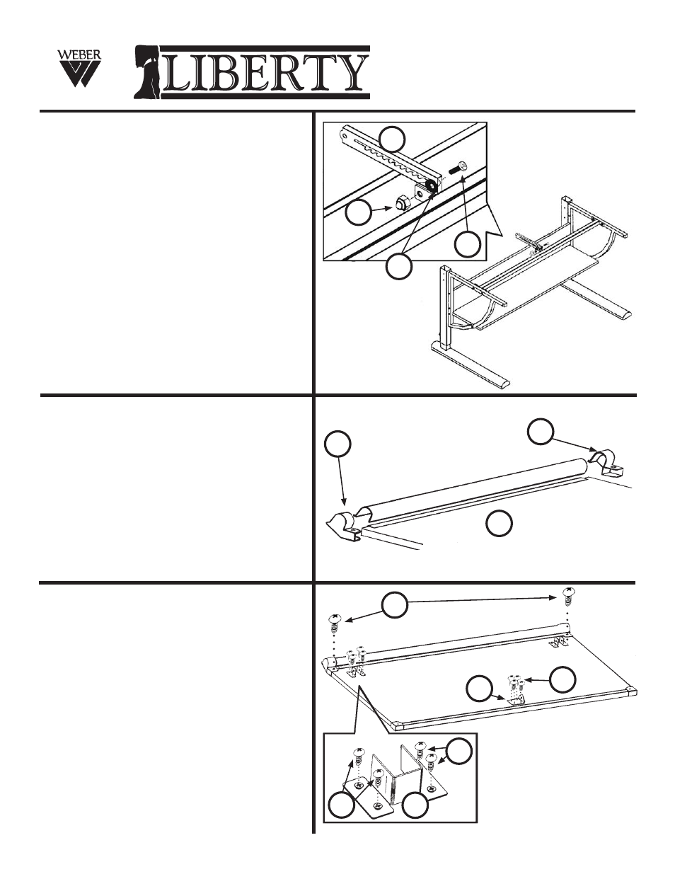
STEP 5
Attachment of Table Top Tilt Mechanism
NOTE: Make sure Tilt Mechanism is on
correct position as show in FIG 5.
Begin by taking the Table Top Tilt
Mechanism (Part O) and attaching it to the
welded block with hole found at the center
of the Top Support. Secure by inserting
one bolt (part D) through the hole of the Tilt
Mechanism (as shown in Zoom of FIG 5)
then add [1] washer (part G), continue going
through the welded block and securing with
a Capped Nut (part I). Tighten Capped Nut
to bolt. See FIG 5.
FIG 5
Position of Tilt
Mechanism (part 4)
& Zoom of Tilt
Mechanism attachment
I
D
O
G
STEP 6
Attachment of Table & Tool Trough Corners
Turn Table Top so that its bottom
Is face up.
Take the [2] Tool Trough Corner protectors
(parts S & T) and slide them onto each end
of the tool trough and two corners of the
table top. See FIG 6. Secure with [1] screw
(part C) to each corner protector. See FIG 7
FIG 6
S
T
7
C
B
B
N
B
M
STEP 7
Attaching Base & Top Brackets
Attach the [2] Base brackets (part N) to the
underside of the top in specified pre-drilled
holes using 4 ea. screws (part B) in each
clamp. Tighten to secure. Repeat with other
side.
Attach Tilt Mechanism Bracket to underside
of the top in specified pre-drilled holes
using 4 ea. screws (part B). Tighten to
secure. Please refer to FIG 7 for proper
positioning of brackets.
FIG 7
Zoom of
attachment
August 08, RPI