Assembly instructions – Martin Universal Design U-DS90W Creation Station User Manual
Page 3
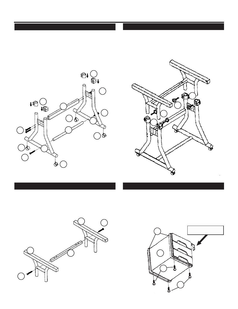
STEP 1] Assembly Base of table
Assembly Instructions:
STEP 3] Complete Base Assembly
Revised June 07- RPI
Pg. 3
Take the top portion and the lower portion of the base that
was just assembled. Insert the top portion into the lower por-
tion, making sure the top ends slide into the collars that are
on the lower portion of the base. Secure with the [4] male
knobs (part H) tightening them into the collars. As shown
below in FIG 3.
2
2
7
5
D
D
D
D
G
G
J
J
K
K
Begin by taking the [2] Lower Base End units (part #2 and
attach the foot bar (part # 7) and the Base Cross Support bar
(part# 5) to each base end using the 1/4” x 2-1/2” Allen Bolts
(part# D). Secure with Allen Wrench (part N), See FIG 1.
Once the base is assembled continue by adding the [4]
collars (part G) to the ends of the base, as pictured below.
Complete Step 1 by inserting [2] locking castors (part J)
into the front of the base end. Complete by inserting the [2]
remaining castors into the rear of the base.
See picture below.
STEP 2] Assemble upper portion of base
Take each upper Base end (left - part #3) and (right - part #4)
and attach to Top Surface Cross Support (part #6) using [2]
1/4” x 2-1/2” Allen bolts (part D). Secure with Allen Wrench
See FIG 2.
F
FIG 1
4
6
D
3
D
FIG 2
H
G
G
H
STEP 4] Drawer Support Assembly
Attach [2] Drawer Supports (part #10) to each set of draw-
ers (part #12) by sliding one onto each end of the drawers
making sure the hooked end is positioned as pictured below
and the 2 holes are on the bottom side of the drawer unit.
Secure each support using [2] M4.2 x 12mm (part F) in each
support. [4] total for each drawer unit. See FIG 4.
FIG 3
FIG 4
Hooked bent end
F
12
10