Nstalling the, Ransmitter, Inishing the – Minka Group F702-VB User Manual
Page 10: Nstallation
WARNING: HOOK UP IN "SERIES ONLY" DO NOT CONNECT THE
HOT AND NEUTRAL WIRES OF THE ELECTRIC CIRCUIT TO THE
TRANSMITTER WALL SWITCH DAMAGE TO THE SWITCH AND
POSSIBLE FIRE COULD OCCUR.
Step 1. Remove the existing wall plate and switch from the wall junction box..
Step 2. Make the electrical connections as shown in (Fig. 17). If your outlet box
has a ground wire (green or bare copper) connect the wall transmitter's ground
wire to it; otherwise connect the wall transmitter's ground wire directly to one of
the screws from the outlet box.
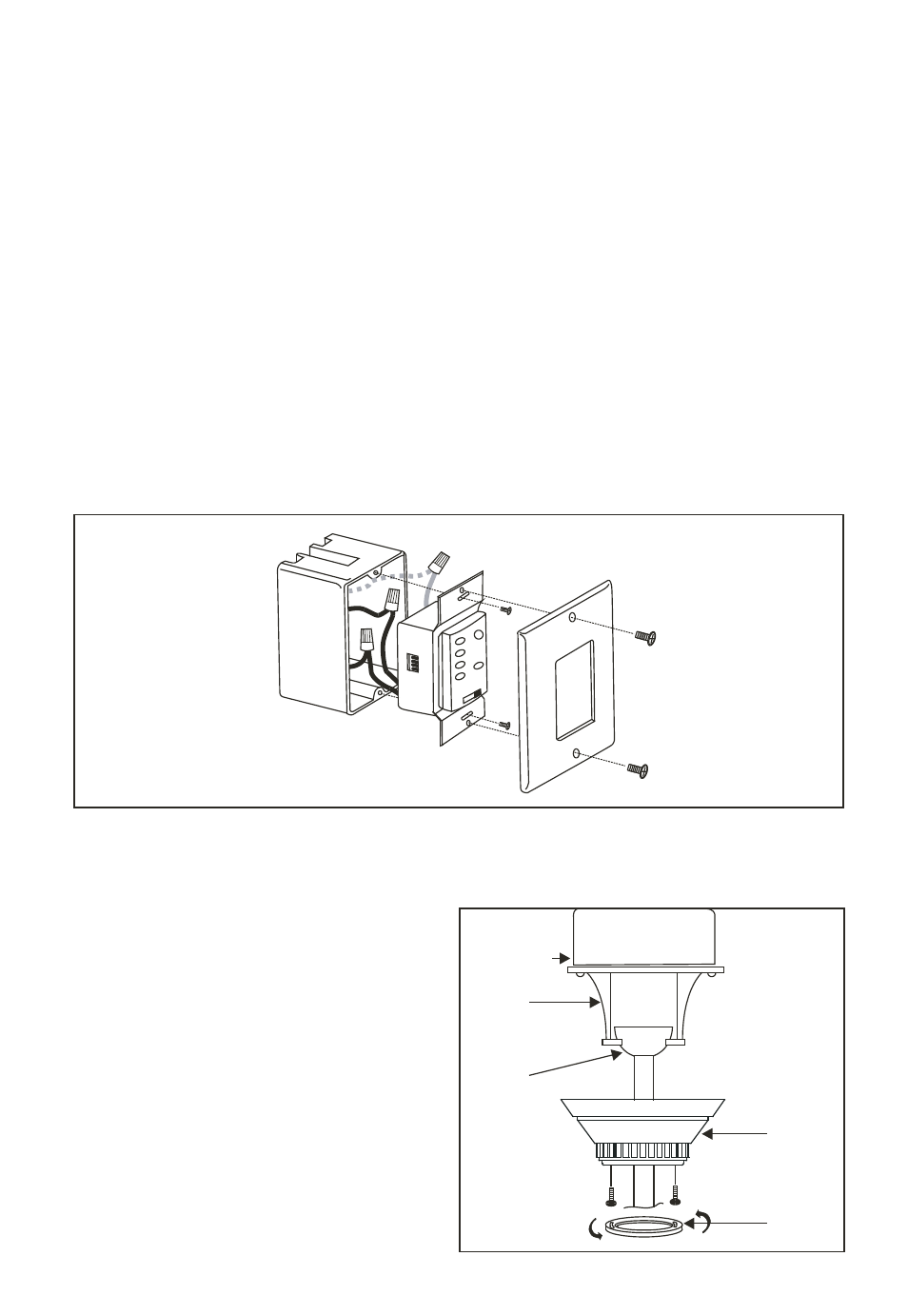
Step 3. (Fig. 18). Carefully tuck the wire connectors inside the junction box.
Secure the wall transmitter with the two screws provided. Attach the decorator
faceplate over the wall transmitter and secure with the two screws provided.
I
NSTALLING THE
W
ALL
T
RANSMITTER
7.
Step 1. Slide canopy up to the ceiling
and over the 2 screws on hanger
bracket. Rotate canopy clockwise,
next, while holding the canopy with
one hand slide the canopy cover over
the screws and rotate clockwise until
tight.
Note; Adjust canopy screws as
necessary until the canopy and canopy
cover are snug. (Fig. 19)
F
INISHING THE
I
NSTALLATION
8.
Fig. 19
Fig. 18
Outlet box
Hanger
bracket
Hanger
ball
Canopy
Canopy
cover