Myron L 762 User Manual
Page 9
Operating Procedures
SECTION 3
Operating Procedures
3.1 GENERAL
This section provides the user with the 750/760 Series Monitor’s
recommended operational checkout procedures. The
illustrations contained in Section 3.2 have been provided to
assist the user in identifying all standard and optionally available
switch and indicator controls.
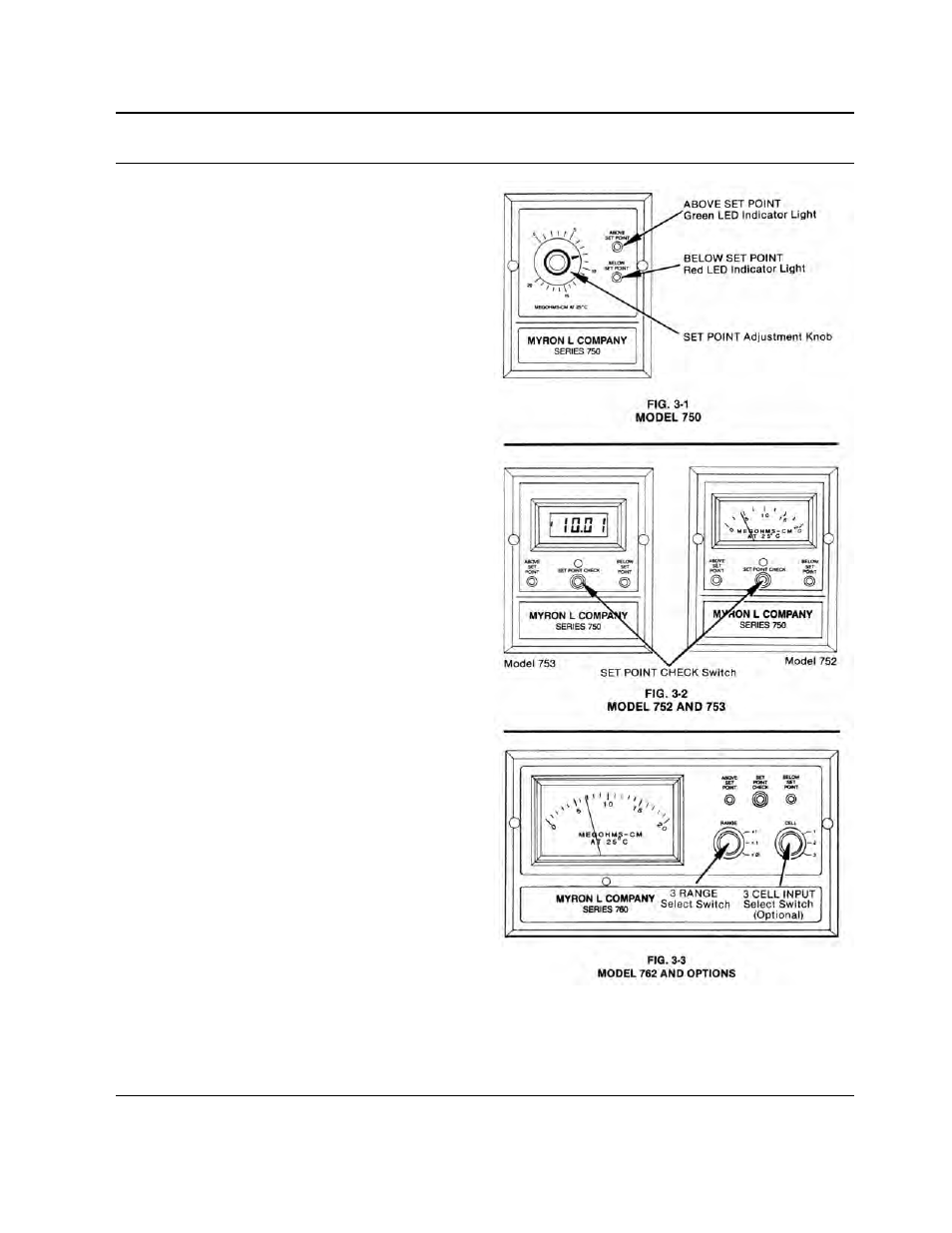
3.2 SWITCH AND INDICATORS CONTROLS
(Standard on all Models)
“ABOVE/BELOW” Set Point Indicators
The green LED indicator light is “ON” only when the
resistance of the water is “ABOVE” the Monitor’s
internal set point adjustment.
The red LED indicator light is “ON” only when the
resistance of the water is “BELOW” the Monitor’s
Internal set point adjustment.
3.2.1 MODEL 750
“SET POINT” Adjustment Knob
Front panel adjustment knob provides immediate
access for adjusting the Controller’s Set Point setting
and to verify its Full Scale reading.
3.2.2 MODEL 752 AND 753
2
1
/
2
" ANALOG METER (752)
The 752’s 2
1
/
2
” (63
mm) linear analog meter provides a
continuous readout of the water being monitored.
DIGITAL LCD METER (753)
The 753’s
1
/
2
" (13
mm) digital LCD meter provides a
continuous readout of the water being monitored.
“SET POINT CHECK” Switch
When the “SET POINT CHECK” switch is depressed
the internal “Set Point” reading is immediately
displayed on the 752’s analog or 753’s digital display
meter.
3.2.3 MODEL 762
4
1
/
2
" ANALOG METER
The 762’s 4
1
/
2
" (114
mm) linear analog meter
provides a continuous readout of the water being
monitored.
7