Myron L 762 User Manual
Page 13
Component Identificaiton, Calibration and Preventive Maintenance
4.3.3 INTERNAL SET POINT ADJUSTMENT
NOTE:
Because the Model 750 is equipped with a standard front panel
“SET POINT” adjustment knob, it does not require an internal
Set Point adjustment setting. Refer to Section 3.3 for procedures
to adjust the 750’s Set Point.
STEP 1 Being careful not to excessively strain cable, unfasten
and remove the Monitor’s front panel.
STEP 2 While simultaneously depressing the “SET POINT
CHECK” switch, turn the Control board’s R31
adjustment screw (See Fig. 4-1) until the desired Set
Point value is indicated on the meter display.
NOTE:
The Monitor’s Set Point setting is based upon the user’s
particular water purity specifications.
STEP 3 After successfully completing STEP 2, remount the
front panel and tightly secure both retaining screws.
4.3.4 0-5 / 0-10 VDC RECORDER BOARD
When properly calibrated to a Monitor’s Full Scale output, the
Recorder interface will provide an adjustable 0-5 through 0-10
VDC.
NOTE:
The Recorder board’s circuitry is not isolated from the Monitor’s
standard Control and Panel board circuitry. Therefore, DO NOT
attempt to connect any user device that could provide a path to
earth ground and/or has an input impedance less than 2000
ohms. Failure to do so may result in faulty operation of the
monitor.
STEP 1 As shown in Fig. 4-5, connect voltmeter probes to the
Recorder board’s TB1 (+) and (-) terminal connectors.
STEP 2 While simultaneously depressing the “SET POINT
CHECK” switch (See Fig. 4-1) turn the Control board’s
Set Point adjust trimmer (R31 ) until the meter displays
the appropriate Full Scale reading.
STEP 3 Next, while still depressing the “SET POINT CHECK”
switch, turn the Recorder board’s R3 Trimmer
adjustment screw (See Fig. 4-5) until the desired full
scale voltage output is indicated on voltmeter.
STEP 4 Reset Set Point to desired setting.
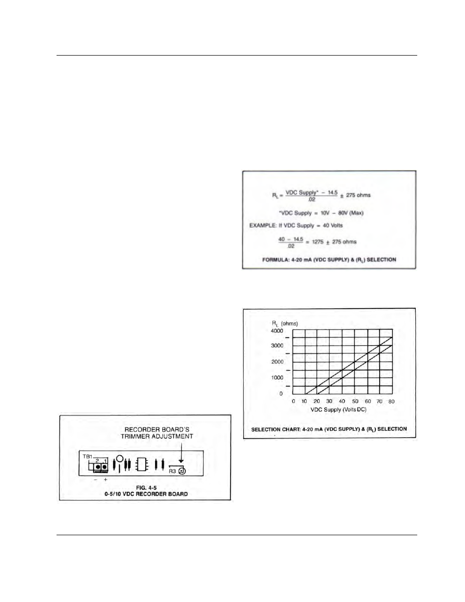
4.3.5 MODEL 753 WITH 4-20 mA OR 4-20D OPTION
NOTE: FOR 420D, PROCEED TO STEP 1.
CAUTION: FOR 4-20mA OPTION ONLY
The proper supply voltage (VDC Supply) and load resistance (R)
must be selected. Failure to do so could result in damage to the
753 optional panel board.
NOTE:
The proper load resistance (in ohms) is found by using the
formula and/or chart as shown below.
11