Myron L 762 User Manual
Page 6
Installation
NOTE:
750/760 Series Monitors are not designed to operate with Cell
cable lengths that exceed 100'(30 meters).
3
If at all possible, mount the monitor at eye level for
viewing convenience.
2.2.1 SURFACE INSTALLATION
Surface mounting will require two (2)
1
/
4
"-20 mounting screws
(supplied). See Fig. 2-1 for hole drilling locations. For ease of
surface mounting, a surface mounting plate is available.
STEP 1 Select your site location, mark and drill the two (2)
required mounting holes.
STEP 2 Place the Monitor’s mounting threads in alignment with
the surface mounting holes.
STEP 3 Insert and securely fasten the two (2)
1
/
4
"-20 mounting
screws.
STEP 4 Slide the enclosure through the panel cutout until its
flange contacts the panel.
STEP 5 Insert mounting screws through the flange mounting
holes and tightly secure.
STEP 6Reconnect all panel cable(s)/wires to Control board.
(See Fig’s 4-1 and 4-2 for panel and Control board
cable connector designations.)
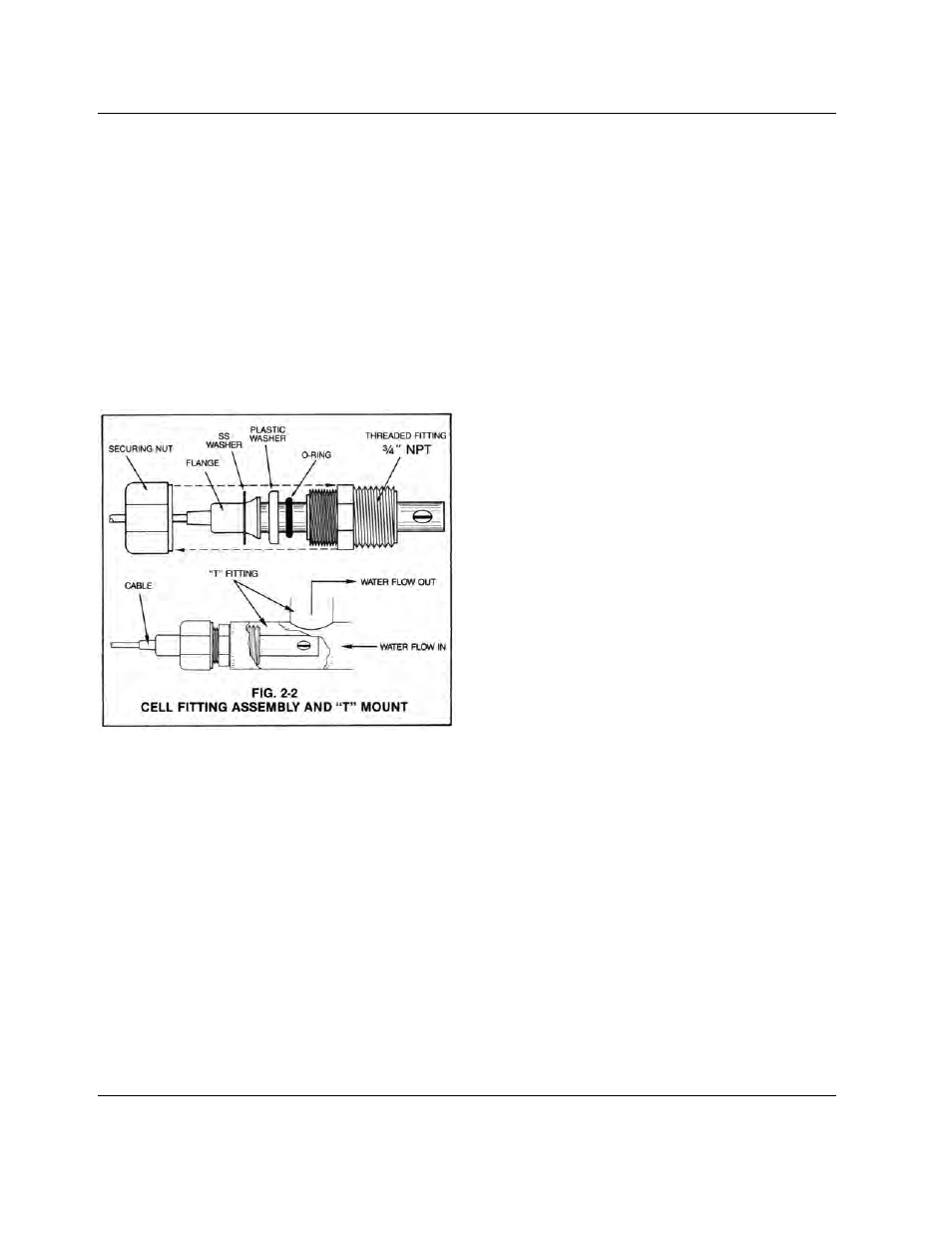
2.2.3 CELL INSTALLATION
Fig. 2-2 illustrates how to properly assemble and install the
CS10 Cell assembly into a “T” type mounting fixture. Improper
assembly could result in damage to equipment and/or property.
A CS10 Cell’s mounting orientation must provide a continuous
and adequate circulation flow to prevent the trapping of air
bubbles within the Cell’s electrode area. Failure to do so will
result in conditions that will prevent the Cell from functioning
properly.
STEP 1 Verify that the Cell’s Fitting assembly is properly
assembled.
STEP 2 Insert the Cell Fitting assembly into the “T” mounting
fixture as shown in Fig. 2-2 and tightly secure.
2.3 ELECTRICAL INSTALLATION
The electrical installation procedures provided in this manual are
common to all 750/760 Series Monitors. See Fig. 2-1 for the
hole dimensions of the enclosure’s various cable access holes.
NOTE:
All water tight cable restraints are user supplied.
2.3.1 MAIN AC POWER INSTALLATION
The following procedures are to be used to install a standard
11
5 VAC main power source. For the procedures to install the
optional 2
30 VAC main power source, the user must first
complete the 11
5V to 230V conversion procedures in Section
2.4.1.
STEP 1 Verify that the facility’s main AC power source is turned
“OFF” or disconnected.
STEP 2 By following the STEPS 2 and 3 in Section 2.2.2,
remove the Monitor’s front panel.
STEP 3 Place the facility’s AC power cord and water tight cable
restraint into the enclosure’s appropriate access hole.
STEP 4 Neatly connect cable wires to the Control board TB1
terminal block connectors as shown in Fig. 2-3.
2.2.2 PANEL MOUNTING
A panel mounting fastening kit is provided with all 750/760
Series Monitors. Panel mounting will require the use of the
fastening kits two (2) 4-40 mounting screws/nuts or two (2) # 4 X
1
/
2
" sheet metal screws. See Fig. 2-1 for panel cutout
dimensions.
STEP 1 Select your site location, mark the appropriate panel
cutout and complete the necessary panel cut.
STEP 2 Carefully unfasten and separate the Monitor’s front
panel from its enclosure.
STEP 3 Disconnect all panel cable(s)/wires from the Monitor’s
Control board.
4