Myron L 762 User Manual
Page 14
Component Identificaiton, Calibration and Preventive Maintenance
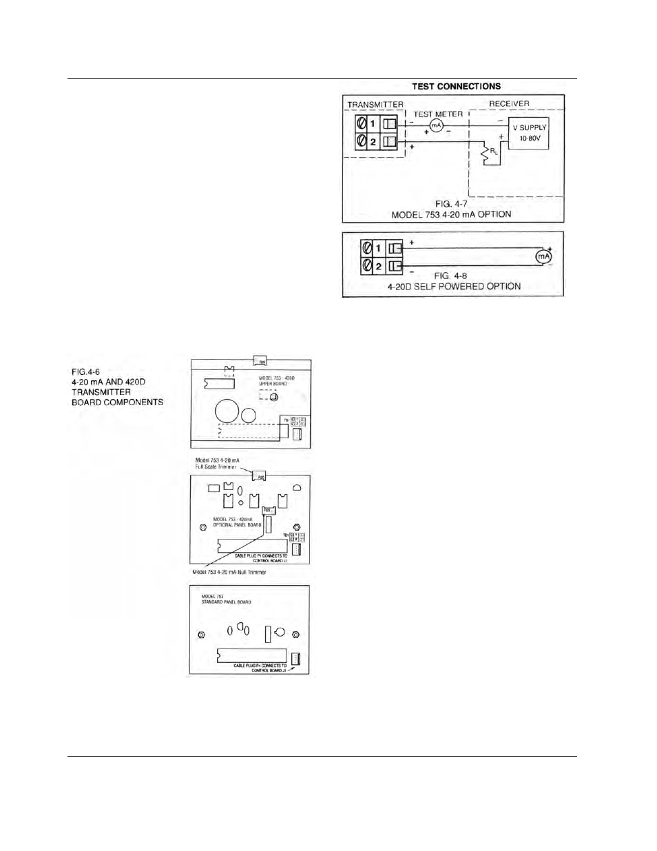
STEP 1 Set the controls of a test meter to read at least 20 mA
and connect it between the positive terminals of the
Transmitter and Receiver as shown in Fig. 4-7 (4-20
mA option) and Fig. 4-8 (4-20D option).
NOTE:
Receiver connected to 420D option should have an
input impedance less than 500 ohms.
STEP 2 Press and hold the “SET POINT CHECK” switch. It
must be depressed during all the following adjustment
steps.
STEP 3 Turn the Set Point trimmer (R31 ) (see Fig. 4-1 ) until
the meter displays a reading of 0.00.
STEP 4 Turn the 4-20 mA Null trimmer (R23) (see Fig. 4-6) until
the test meter indicates 4 mA.
STEP 5 Readjust the Set Point trimmer (R31 ) until the meter
displays 1999 (decimal point omitted).
STEP 6Turn the 4-20 mA Full Scale trimmer (R20) (see Fig. 4-
6) until the test meter indicates 20 mA.
STEP 7 Repeat STEP 3 through STEP 6, readjusting as
required.
STEP 8 Reset the set point to the desired setting. Release the
“SET POINT CHECK” switch.
4.4
PREVENTIVE CARE
Although designed to minimize operating problems, the Myron L
Company recommends that the following Preventive Care
procedures be observed.
1
Try to prevent exposure to excessive heat and
moisture.
2
The Monitor’s main AC power source must be
protected against excessive voltage spikes.
3
Take care not to damage Monitor during handling.
NOTE:
Daily, weekly or monthly maintenance schedules are based
upon the frequency of use and the severity of the Monitor’s
environment and operating conditions.
STEP 1 Repeat the Monitor’s Check-Out procedures and/or
isolate possible troubleshooting symptoms.
STEP 2 Check all cable connections to ensure that they are
free of moisture and contamination.
STEP 3 Inspect and replace damaged component boards and
cable assemblies.
STEP 4 Remove and clean sensor with soap and water. Rinse
thoroughly.
12