頁面 5, Gnd lift – MIPRO ACT-717 Single-Channel True Diversity Receiver User Manual
Page 5
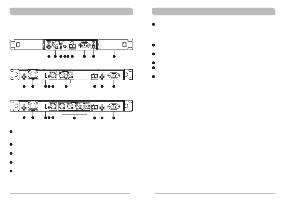
Rear Panel:
ACT-717 / ACT-717B Single-Channel True-Diversity Receiver
6
10
8
11
12
14
13
15
ACT-727 / ACT-727B Dual-Channel True-Diversity Receiver
6
7
8
9
10
12
13
14
12
13
14
ACT-747 / ACT-747B Four-Channel True-Diversity Receiver
6
7
8
9
10
Rear Antenna “B” Input Connector: The “B” antenna can be installed directly
to this antenna connector which also provides power to an optional antenna
booster.
Ventilation Fan: Ensures stable performance in long hours of operation under
high temperature environments.
Level Switch: "0dB" selection is for "Microphone level" output. “+16dB" selection
is for “AUX level” output. “-6dB” selection is for half of cable microphone volume.
Mixed AF Output Jack: A balanced output jack for mixed AF signals from all
installed channels; 3 output levels to choose from.
Balanced Audio Output Jack: XLR type connector provides balanced audio
output signal from this jack to the mixer, and output level is selectable from
among 3 levels: “-6dB”, “0dB” and “+16dB”.
8
10
6
7
9
16
CH 1
CH 2
MIXED
ANTENNA A
+8V DC BIAS
ANTENNA B
+8V DC BIAS
REMOTE
OUT
IN
3: COLD -
1: GND
+
2: HOT
3
2
1
LEVEL
This connector can not be connected
to telecommunication networks.
BALANCED OUT
AC INPUT: 100~240V
-6dB
0dB
GND
LIFT
+16dB
CH 1
CH 2
CH 3
CH 4
MIXED
REMOTE
ANTENNA A
+8V DC BIAS
ANTENNA B
+8V DC BIAS
OUT
IN
3: COLD -
1: GND
+
2: HOT
3
2
1
LEVEL
This connector can not be connected
to telecommunication networks.
BALANCED OUT
AC INPUT: 100~240V
-6dB
0dB
GND
LIFT
+16dB
16
16
True Diversity Receivers
True Diversity Receivers
4
5
Unbalanced Audio Output Jack: ¼” PHONE PLUG type connector provides
unbalanced audio output signal from this jack to the mixer (ACT-717/ACT-717B
only). Output level is selectable from among 3 levels: “-6dB”, “0dB” and +10dB
(the switch will show +16dB on the receiver, but actually puts out +10dB on the
unbalanced jack).
Network Interface Connector: For linking the receivers to a computer system-
monitoring program.
Rear Antenna “A” Input Connector: The A antenna can be installed directly to
this antenna connector which also provides power to an optional antenna booster.
AC Power Socket: The input socket for AC power ranging from 100V ~ 240V AC.
Rack-Mount Brackets: To install the receiver into a standard EIA 19-inch rack
case.
LIFT/GND switch: Lifts ground from Pin 1 of the XLR connector. (GND= default).
14
13
12
11
15
16