頁面 14 – MIPRO ACT-717 Single-Channel True Diversity Receiver User Manual
Page 14
1. MIPRO ACT receivers have an advanced computer network-interfaced controlling
system.
2. Wiring Instructions
!
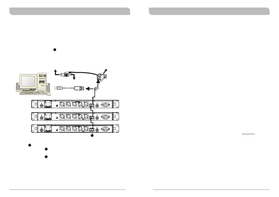
The network interface of ACT-717/727/747、ACT-717B/727B/747B receivers is
the ''REMOTE'' connector that can be linked to a computer by a MIPRO-DVU or
MIPRO-DVJ hardware device. By using a RS-232 or USB connector, you can link
to a computer through the RS-232 COM PORT or USB PORT. (See diagram
below)
!
Plug one side of the provided cable (w/ RJ-11 connectors) to the REMOTE OUT
socket on the rear of the receiver and the other end of the phone cable to the
REMOTE IN socket on the rear of the second receiver. Repeat this connection
for each receiver in the system as per the illustration. Finally, connect the
REMOTE IN socket on the rear of the first receiver to the MIPRO-DVU or
MIPRO-DVJ.
!
This system can link, monitor and control up to 64 receiver channels
simultaneously.
!
The connecting cable to the computer can be up to 300 meters (330 yards) in
length; however, signal stability decreases the longer the cable distance.
Therefore, the cable length is recommended not to exceed 100m (110 yards) to
maintain the highest quality as well as a high speed of transmission.
RX1
RX2
RX3
MIPRO DVU
MIPRO DVJ
OR
PC
CH 1
CH 2
CH 3
CH 4
MIXED
REMOTE
ANTENNA A
+8V DC BIAS
ANTENNA B
+8V DC BIAS
OUT
IN
3: COLD -
1: GND
+
2: HOT
3
2
1
+16dB
-6dB
0dB
LEVEL
This connector can not be connected
to telecommunication networks.
BALANCED OUT
AC IN PUT: 1 00~240V
CH 1
CH 2
CH 3
CH 4
MIXED
REMOTE
ANTENNA A
+8V DC BIAS
ANTENNA B
+8V DC BIAS
OUT
IN
3: COLD -
1: GND
+
2: HOT
3
2
1
+16dB
-6dB
0dB
LEVEL
This connector can not be connected
to telecommunication networks.
BALANCED OUT
AC IN PUT: 1 00~240V
CH 1
CH 2
CH 3
CH 4
MIXED
REMOTE
ANTENNA A
+8V DC BIAS
ANTENNA B
+8V DC BIAS
OUT
IN
3: COLD -
1: GND
+
2: HOT
3
2
1
+16dB
-6dB
0dB
LEVEL
This connector can not be connected
to telecommunication networks.
BALANCED OUT
AC IN PUT: 1 00~240V
Connect to RS-232 jack on PC
Connect to keyboard jack on PC
Connector of keyboard
should plug in here
Connect to USB
jack on PC
COMPUTER NETWORK INTERFACE OPERATION
12
12
12
12
12
True Diversity Receivers
True Diversity Receivers
1.
Since the installation of the antenna influences the operating efficiency of the
receiver, the most important rule is to minimize the distance as much as possible
between the receiving antenna and the microphone for the best reception and
performance.
2.
Use MIPRO supplied antennas to ensure proper receiver sensitivity.
3.
A built-in worldwide approved switching power supply assures stable performance
in the range of 100~240V AC power input.
4.
Please note the main disconnected device is the AC Inlet.
5.
The antenna socket provides an 8V DC biased output. Therefore, shorting on the
antenna socket should be avoided. Temporary shorting on the antenna socket will
not affect system performance; however, continuous shorting on the antenna
socket will cause permanent system damage.
6.
If extended reception distance is needed, installing a MIPRO directional antenna kit
(AT-90W) will increase the reception distance.
7.
Proper antenna distribution is vital to achieving ideal performance from multiple
wireless systems operating in the same environment. To greatly reduce antenna
clutter in multi-system installations, a MIPRO AD-707/AD-707a UHF antenna
divider system is recommended. Each AD-707/AD-707a supports up to four UHF
diversity receivers to operate from a single pair of antennas. When combined with
an AT-70A omnidirectional extension antenna and an AT-70B antenna booster or
an AT-90W directional antenna, the AD-707/AD-707a antenna divider provides
optimal signal reception with minimal dropouts or interference.
8.
Preset non-interfering channels within the same channel group are recommended
to ensure optimum performance from multiple wireless systems installed in the
same venue. Use of preset non-interfering channels from different channel
groups may cause interference, thus is not recommended.
GENERAL TIPS FOR IMPROVING SYSTEM PERFORMANCE
22
23