頁面 6, 8v dc bias, Out in – MIPRO ACT-82a Wideband Dual-Channel Digital Receiver User Manual
Page 6
6
7
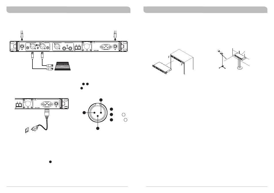
(Figure 3)
(Figure 5)
Receiver Installation
1. Install 2 separate antennas on the antenna inputs connector on the rear panel. (See Figure 3).
2. Connect the AC power cable to the AC Mains Power Socket , then plug the other end into an AC
outlet having the correct voltage and rating. (See Figure 4)
20
19
3. Audio Output Connection:
(Figure 4)
10
!
Balanced Output Switch: 4 levels of output gain are available: (10dB, 0dB,-6dB, -12dB) Select
the most appropriate output level to interface with your mixer or amplifier. If distortion is
experienced, adjust the level control to a lower setting until the desired output is attained.
!
Balanced Output: Using audio output cables with 3 pin "XLR" type connectors, connect one end
to the balanced output socket of the receiver, and the other end to the "MIC IN" input of the
mixer or amplifier, as shown in Figure 3. (The configuration of the 3-pin connector is as shown in
Figure 5.)
!
Electric Guitar Output: Using an XLR to 1/4” Jack type connector cable (use Pins 1 and 2 only)
connect to guitar input socket on amplifier. Make sure that the gain level is set at 0dB on both
receiver and transmitter.
ANTENNA B
+8V DC BIAS
+8V DC BIAS
ANTENNA A
REMOTE
OUT
IN
AC INPUT: 100~240V
-6
0
10
-1
2
This connector can not be connected
to telecommunication networks.
LIFT
GND
ANALOG
GAIN (dB)
BALANCED OUT CH2
BALANCED OUT CH1
GAIN (dB)
WORDCLOCK SYNC
IN
DIGITAL
CH 1 + CH 2
AES/EBU OUT
OUT
-6
0
10
-1
2
+8V DC BIAS
ANTENNA A
REMOTE
OUT
IN
AC INPUT: 100~240V
This connector can not be connected
to telecommunication networks.
COLD
-
GND
+
HOT
1
2
3
2
1
3
12
(Figure 7)
4. The rack ears are pre-drilled with 4 holes to enable fitting of the receiver into an EIA standard 19-
inch rack case (See Figure 6). For front antenna installation, remove the two plugs on the rack
mount ears and install an optional pair of FBC-71 rear-to-front cables.
5. For best reception and performance, ensure that the receiver is installed at least 1 metre (3 feet)
above the ground and away from EMI / RFI “noise” sources. In addition, place the
transmitter/microphone at least 1 metre (3 feet) away from the receiving antenna, as shown. (See
Figure 7)
Ground
W
al
l
1
m
1m
1m
1m
(Figure 6)
Receiver Operating Tips
!
!
!
!
!
Prior to powering on the receiver, ensure all transmitters are turned off and the mixer's volume
control is set to minimum.
Normally, the RF meter level illuminates fully when a transmitter is powered on to indicate the
receiver is ready for operation. Once an audio signal is received from the transmitter, the AF (audio)
meter level will also illuminate based on signal level. If the meter or indicator does not indicate or
there is no audio output, the system may not be set up properly. Re-check that the transmitter has
fresh batteries and is turned on and the receiver and transmitter are on the same frequency. If not,
the transmitter will need to be set up via the ACT sync function.
The microphone output level in normal use should be adjusted at the amplifier or mixer. There is no
need to adjust output levels at the receiver itself once initial setup is completed.
The antenna inputs provide an 8-volt DC bias and are designed to work with MIPRO antenna boosters
and active antennas. If the connecting cable is longer than 10 metres (approx. 30'), it is advisable to
install an antenna booster to ensure optimum reception.
Antenna dividers and receivers must match the same frequency band (i.e. both should be marked
6B, 6C etc.)
Encrypted Digital Wideband Diversity Receiver
Encrypted Digital Wideband Diversity Receiver