頁面 13 – MIPRO ACT-82a Wideband Dual-Channel Digital Receiver User Manual
Page 13
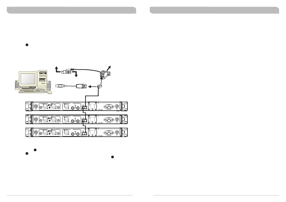
Computer Network Interface Operation
General Tips for Improving System Performance
1. MIPRO ACT receivers are fitted with an ACT-BUS interface to enable remote control and monitoring
via a PC-based control system. To enable this to communicate, an optional MIPRO interface adapter
and software package is required.
2. Wiring Instructions
!
Network interfacing of the ACT-82a receivers is achieved via the REMOTE IN of the Network Interface
Connector . This enables the receiver(s) to be linked to a computer using a MIPRO-DVJ (Serial)
or MIPRO-DVU (USB) interface connector. Using the RS-232 or USB connector, you can link to a
computer through the RS-232 COM port or USB port. (See diagram below)
17
MIPRO DVU
MIPRO DVJ
OR
PC
Connect to RS-232 jack on PC
Connect to keyboard jack on PC
Connector of keyboard
should plug in here
Connect to USB
jack on PC
!
Plug one side of the supplied telephone-type cable (RJ-11 connectors) to the REMOTE OUT
socket of the on the rear of the receiver and the other end of the cable to the REMOTE IN
socket on the rear of the second receiver. Repeat this connection for each receiver in the
system as per the illustration above. Finally, connect the REMOTE IN socket on the rear of
the first receiver to the MIPRO-DVU or MIPRO-DVJ.
!
The system can link, monitor and control up to 64 receiver channels simultaneously.
!
The connection cable to the computer can be up to 300 metres (330 yards) in length. However,
signal stability and data transmission speed decreases as cable distance gets longer. Therefore
it is recommended not to exceed 100m (110 yards) to maintain the highest data quality as well
as a high transmission speed.
17
17
17
!
Since the installation of the antenna influences the operating efficiency of the receiver, the most
important rule is to minimise the distance as much as possible between the receiving antenna and
the microphone for the best reception and performance.
!
Use MIPRO supplied antennas to ensure proper receiver sensitivity.
!
A built-in worldwide approved switching power supply assures stable performance in the range of
100-240V AC mains power input.
!
The antenna socket provides an 8V DC biased output. Therefore, shorting the antenna socket should
be avoided. Temporary shorts on the antenna socket will not affect system performance (provided
the short is removed), however, a continuous short on the socket may cause permanent system
damage.
!
If extended reception distance is required, installing a MIPRO wideband active directional antenna kit
(AT-90W) will increase antenna performance and thus achieve better range.
!
Proper antenna distribution is vital to achieving ideal performance from multiple wireless systems
operating in the same environment. To greatly reduce antenna clutter in multi-system installations, a
MIPRO AD-707a UHF wideband antenna divider system is recommended. Each AD-707a supports up
to four UHF diversity receivers to operate from a single pair of antennas. When combined with an
AT-70A omni-directional extension antenna and an AT-70B antenna booster or an AT-90W wideband
active directional antenna, the AD-707a antenna divider provides optimal signal reception with
minimal dropouts or interference. Note that the AD-707a antenna divider must match the same band
designation (7A,7B,8A,8B etc.) as the receiver to ensure proper operation.
!
MIPRO's factory preset “interference-free” channels within the same channel group are recommended
to ensure optimum performance from multiple wireless systems installed in the same venue. Use of
preset “interference-free” channels from different channel groups may cause interference due to
intermodulation issues, and is therefore not recommended.
20
21
RX1
RX2
RX3
ANTENNA B
+8V DC BIAS
+8V DC BIAS
ANTENNA A
REMOTE
OUT
IN
AC INPUT: 100~240V
-6
0
10
-1
2
This connector can not be connected
to telecommunication networks.
LIFT
GND
ANALOG
GAIN (dB)
BALANCED OUT CH2
BALANCED OUT CH1
GAIN (dB)
WORDCLOCK SYNC
IN
DIGITAL
CH 1 + CH 2
AES/EBU OUT
OUT
-6
0
10
-1
2
ANTENNA B
+8V DC BIAS
+8V DC BIAS
ANTENNA A
REMOTE
OUT
IN
AC INPUT: 100~240V
-6
0
10
-1
2
This connector can not be connected
to telecommunication networks.
LIFT
GND
ANALOG
GAIN (dB)
BALANCED OUT CH2
BALANCED OUT CH1
GAIN (dB)
WORDCLOCK SYNC
IN
DIGITAL
CH 1 + CH 2
AES/EBU OUT
OUT
-6
0
10
-1
2
ANTENNA B
+8V DC BIAS
+8V DC BIAS
ANTENNA A
REMOTE
OUT
IN
AC INPUT: 100~240V
-6
0
10
-1
2
This connector can not be connected
to telecommunication networks.
LIFT
GND
ANALOG
GAIN (dB)
BALANCED OUT CH2
BALANCED OUT CH1
GAIN (dB)
WORDCLOCK SYNC
IN
DIGITAL
CH 1 + CH 2
AES/EBU OUT
OUT
-6
0
10
-1
2
Encrypted Digital Wideband Diversity Receiver
Encrypted Digital Wideband Diversity Receiver