Specification – Beijer Electronics NA-9379 User Manual
Page 24
NA-9379
Specification
Revision 1.02
FnBus PIO N/A
Page 24
+ 0x17(+23)
0x2017(8215)
0x2037(8247)
0x2057(8279)
…….
0x23D7(9175)
0x23F7(9207)
+ 0x18(+24)
0x2018(8216)
0x2038(8248)
0x2058(8280)
…….
0x23D8(9176)
0x23F8(9208)
+ 0x19(+25)
0x2018(8217)
0x2038(8249)
0x2058(8281)
…….
0x23D9(9177)
0x23F9(9209)
+ 0x1A(+26)
0x201A(8218)
0x203A(8250)
0x205A(8282)
…….
0x23DA(9178)
0x23FA(9210)
+ 0x1B(+27)
0x201B(8219)
0x203B(8251)
0x205B(8283)
…….
0x23DB(9179)
0x23FB(9211)
+ 0x1C(+28)
0x201C(8220)
0x203C(8252)
0x205C(8284)
…….
0x23DC(9180)
0x23FC(9212)
+ 0x1D(+29)
0x201D(8221)
0x203D(8253)
0x205D(8285)
…….
0x23DD(9181)
0x23FD(9213)
+ 0x1E(+30)
0x201E(8222)
0x203E(8254)
0x205E(8286)
…….
0x23DE(9182)
0x23FE(9214)
+ 0x1F(+31)
0x201F(8223)
0x203F(8255)
0x205F(8287)
…….
0x23DF(9183)
0x23FF(9215)
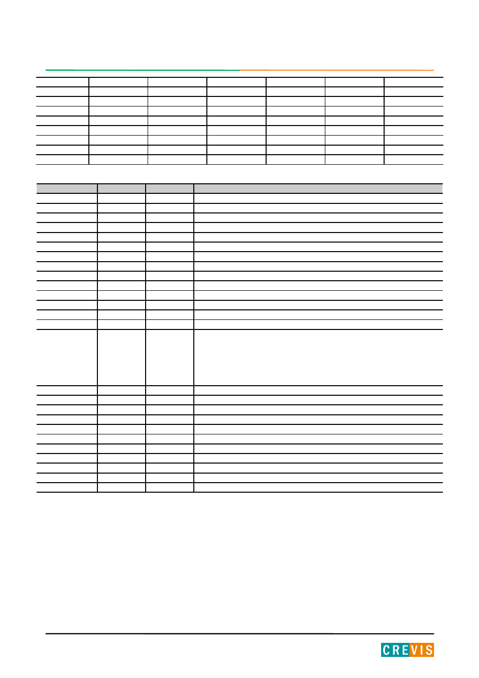
Address Offset
Access
Type, Size
Description
+ 0x00(+0)
Read
1word
Slot module id. Refer to Appendix A.1 Product List.
+ 0x01(+1)
Read
1word
Expansion Slot IO code. Refer to Table IO Data Code Format.
+ 0x02(+2) **
Read
1word
Input start register address of input image word this slot.
+ 0x03(+3) **
Read
1word
Input word’s bit offset of input image word this slot.
+ 0x04(+4) **
Read
1word
Output start register address of output image word this slot.
+ 0x05(+5) **
Read
1word
Output word’s bit offset of output image word this slot.
+ 0x06(+6) **
Read
1word
Input bit start address of input image bit this slot.
+ 0x07(+7) **
Read
1word
Output bit start address of output image bit this slot.
+ 0x08(+8) **
Read
1word
Size of input bit this slot
+ 0x09(+9) **
Read
1word
Size of output bit this slot
+ 0x0A(+10)**
Read
n word
Read input data this slot
+ 0x0B(+11)**
Read/Write
n word
Read/write output data this slot
+ 0x0C(+12) *
Read/Write
1word
Inactive slot, 0x0000:active, 0x0001:inactive
+ 0x0E(+14)
Read
1word
ST-number, if ST-1218, returns 0x1218
+ 0x0F(+15)
Read
String
upto 74byte
First 1word is length of valid character string.
If ST-1218, returns
“00 1E 52 54 2D 31 32 33 38 2C 20 38 44 49 2C 20 32 34 56 64 63 2C 20
55 6E 69 76 65 72 73 61 6C 00 00”
Valid character size = 0x001E =30 characters,
“ST-1218, 8DI, 24Vdc, Sink”
+ 0x10(+16)
Read
1word
Size of configuration parameter byte
+ 0x11(+17)**
Read/Write
n word
Read/write Configuration parameter data, up to 8byte. ***
+ 0x12(+18)
Read
1word
Size of memory byte.
+ 0x13(+19)**
Read/Write
n word
Read/write Memory data. Offset of memory is fixed with 0
+ 0x14(+20)**
Read/Write
n word
Read/write Memory data. First 2byte of write data is memory offset.
+ 0x15(+21)
Read
2word
Product code Refer to Appendix A.1 Product List.
+ 0x16(+22)
Read
2word
Catalog number. Refer to Appendix A.1 Product List.
+ 0x17(+23)
Read
1word
Firmware Revision
+ 0x18(+24)
Read
1word
FnBus Revision
+ 0x1A(+26)
Read/Write
n word
Reserved. Read/write expansion class access. (vendor only)
+ 0x1B(+27)
Read/Write
n word
Reserved. Read/write maintenance data access. (vendor only)
* After the system is reset, the new “Set Value” action is applied.
** Nothing of output, input, memory or configuration parameter corresponding slot returns Exception 02.
*** Slot Configuration parameter saved by internal EEPROM during power cycle until slot position changed.
*** All of output modules and special modules have the slot configuration parameter data.
PRELIMINARY