Installing a gate, Prepare railing, Assemble railing panel – AZEK Rail User Manual
Page 2: Attach aluminum side rails
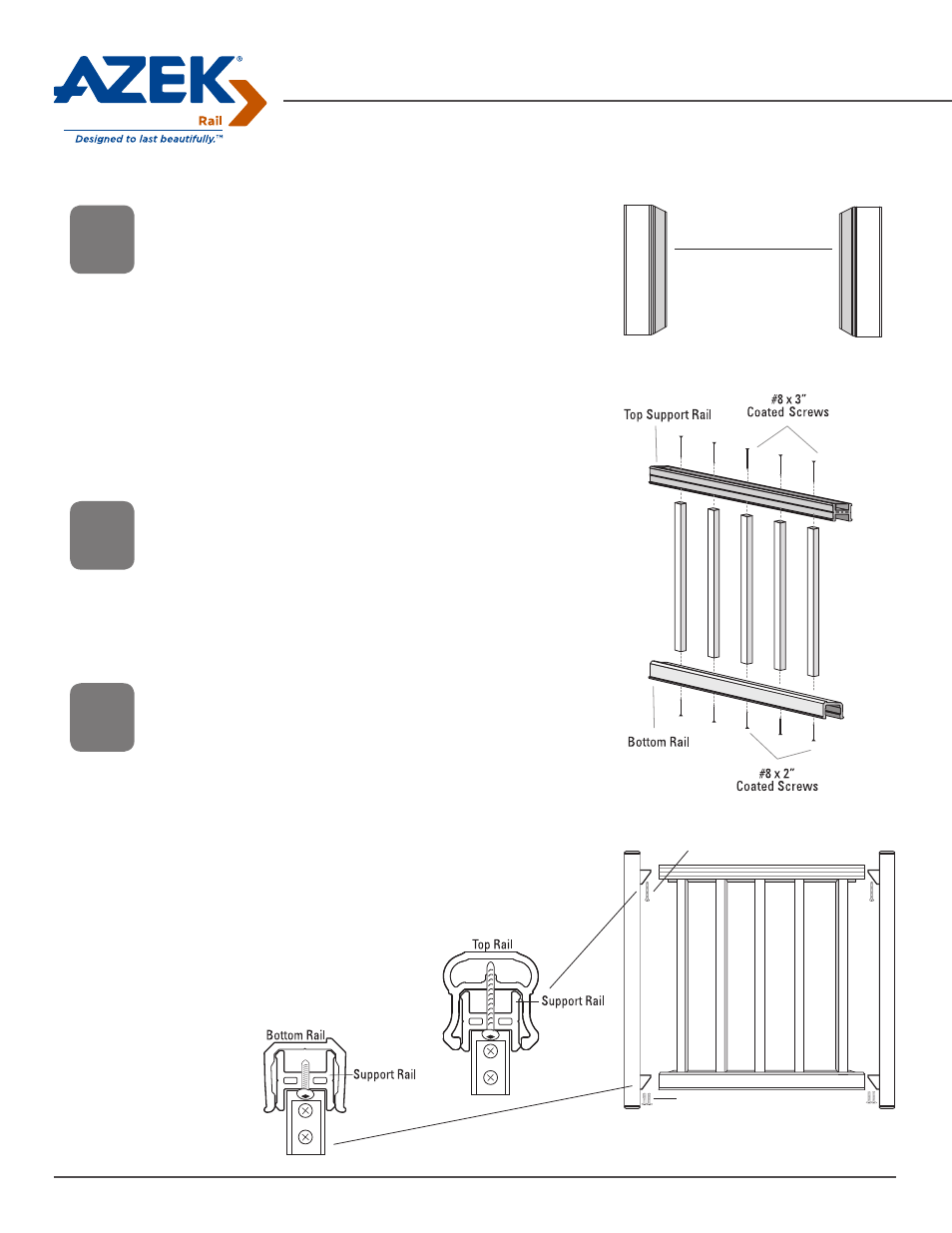
Installing a Gate
Prepare Railing
• Measure the distance between the posts near the top and bottom of
the posts. As long as both posts are plumb, this should be the same
distance.
• All rails should be cut 5-1/4” shorter than the opening for your gate.
• Cut the Top Rail and bottom Support Rail to length.
• Determine baluster layout on top Support Rail and Bottom Rail. To
maximize the baluster spacing between the end balusters and the
aluminum Side Rails, center the rail measurement on a pre-drilled hole
or halfway between two pre-drilled holes. The space between the end
balusters and the aluminum Side Rails should not exceed
4” or should not be less than 1-1/2”. Cut top Support Rail and Bottom
Rail to length.
Assemble Railing Panel
• Position balusters along the top Support Rail, aligning them with the
pre-drilled holes. Secure using #8 x 3” coated screws.
• Position Bottom Rail, using the lip to help align Balusters. Secure
using #8 x 2” coated screws.
• Tip for Bottom Rail: partially drive screws into all balusters before
driving them in completely.
Attach Aluminum Side Rails
• On a flat surface, position the Side Rails on both sides of the
assembled rail section. Place the bottom Support Rail over the
lower brackets as shown.
• Using the brackets as a guide, mark and pre-drill two holes in the
bottom Support Rail at each end using a 11/64” drill bit. Attach the
bottom Support Rail to the lower brackets with four ¼” x 1” screws.
• Place the Bottom Rail of the assembled rail section over the bottom
support rail while lowering the top of the section onto the upper
brackets.
• Place the Top Rail over the top Support Rail. Using the brackets as a
guide, mark and pre-drill a hole through the top Support Rail and lower
cross rib of the Top Rail with an 11/64” drill bit. Secure the
Top Rail and assembled rail section to the upper
brackets with two ¼” x 1-3/4” screws.
• If access is restricted to this bracket
because of the last baluster, use a
ratchet to drive the screws.
Gate opening
minus 5-1/4”
1/4” x 1-3/4” Screw (frame color)
1/4” x 1” Screw (frame color)
1
2
• Consult your local building codes for gate requirements
3
Page 2