Vaddio Quick-Connect Universal CAT-5 User Manual
Page 18
WallVIEW Universal CCU Cat-5 Version
Vaddio WallVIEW Universal CCU Cat-5 Version. Document Number 342-0512 Rev C Page 18 of 20
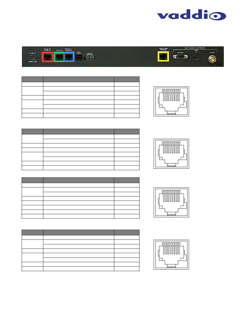
Appendix 1: Cable Pin-outs for the Quick-Connect CCU System
Quick-Connect CCU Pin-out Assignments:
Power Connector RJ-45 (Red)
Pin #
Function
Pairs
Pin - 1
Power +
1
Pin - 2
Power -
1
Pin - 3
Power +
2
Pin - 4
Power -
3
Pin - 5
Power +
3
Pin - 6
Power -
2
Pin - 7
Power +
4
Pin - 8
Power -
4
RS-232 IN RJ-45 (Green)
Pin #
Function
Pairs
Pin - 1
N/A
Not Used
Pin - 2
N/A
Not Used
Pin - 3
N/A
Not Used
Pin - 4
N/A
Not Used
Pin - 5
N/A
Not Used
Pin - 6
Digital GND
Pin - 7
RXD (from TXD of control source)
4
Pin - 8
TXD (to RXD of control source)
4
RS-232 OUT RJ-45 (Blue)
Pin #
Function
Pairs
Pin - 1
N/A
Not Used
Pin - 2
N/A
Not Used
Pin - 3
N/A
Not Used
Pin - 4
N/A
Not Used
Pin - 5
N/A
Not Used
Pin - 6
Digital GND
Pin - 7
TXD (to RXD of control source)
4
Pin - 8
RXD (from TXD of control source)
4
Video (HSDS-differential) RJ-45 (Yellow)
Pin #
Function
Pairs
Pin - 1
N/A
Not Used
Pin - 2
N/A
Not Used
Pin - 3
Y+
2
Pin - 4
PB+
33
Pin - 5
PB GND
3
Pin - 6
Y GND
2
Pin - 7
PR+
4
Pin - 8
PR-
4
RS-232
IN
12345678
12345678
RS-232
OUT
12345678
12345678
36 VDC TO
CAMERA
VIDEO FROM
CAMERA