Attaching the flash plate (fcn) to the bracket, Attaching your flash cord to the digital pro-e, Attaching accessories (ap, mc, ft-jr) – Custom Brackets QRS-2 User Manual
Page 2
FCN
Use the examples below to set your FCN. Screw cord onto plate and adjust the plastic piece so that
it is next to the cord.
Nikon SC-29
Nikon SC-28 &
Canon Cords
Canon
Off-Camera Cord 2
Off-Camera Cord OC-E3
Flash Screw
Flash Cord Here
Nikon SC-17
Nikon SC-28
Flash Cord Here
Flash Cord Here
Nikon SC-29
Attaching your flash cord to the FCN
Using the flash lock on the
Digital PRO-M, Digital PRO, QRS-H2, QRS-E2, QRS-2
The flash lock knob will lock the flash in any tilt position desired.
1 - Loosen the flash lock knob, tilt the flash to the desired position. Then retighten the flash lock knob.
Digital PRO-M &
Digital PRO Bottom Upright
Flash lock knob
Flash receiver
QRS-H2, QRS-E2
& QRS-2 Upright
**QRS-2 not shown
Flash lock knob
Flash receiver
Attaching the flash plate (FCN) to the bracket
Loosen the flash receiver knob. Slide the flash
plate onto the flash receiver until it stops. Then
retighten the flash receiver knob.
(Shown with Nikon SC-17 cord)
Flash receiver
Flash receiver knob
Flash plate
Attaching your flash cord to the Digital PRO-E
Use the steps below to set your anti-twist plates (first time installation only).
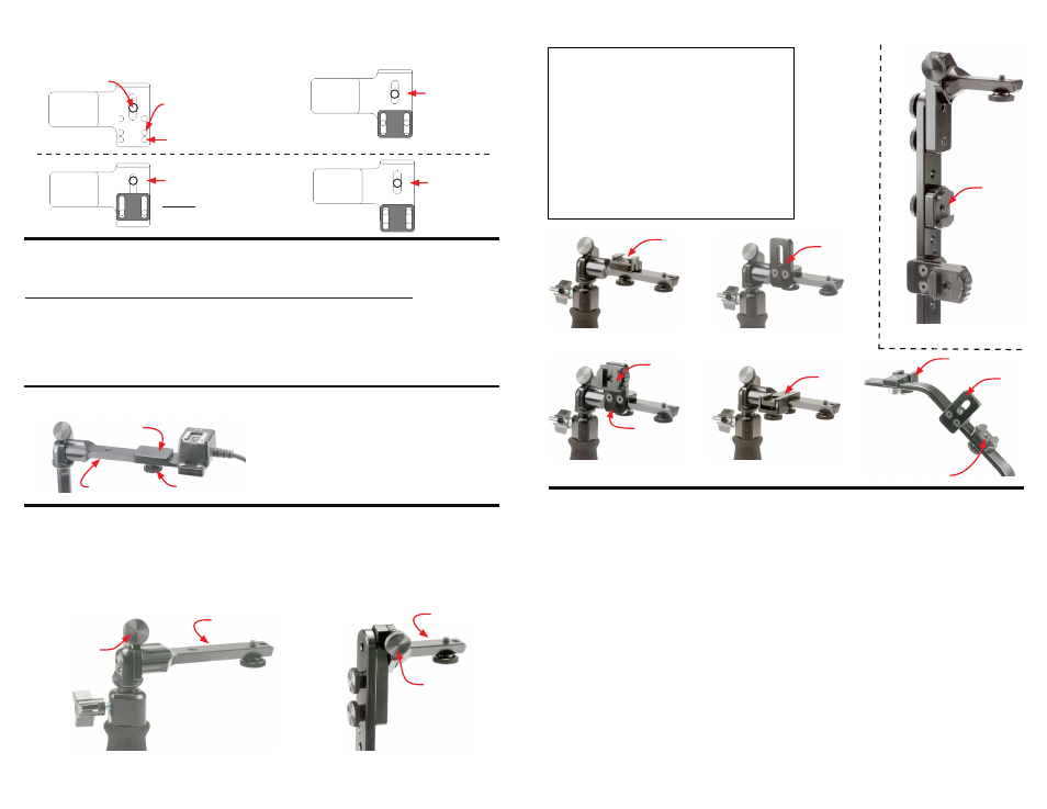
Attaching accessories (AP, MC, FT-JR)
Figure #19
Figure #14
MC
MC attached
to AP
MC
FT-JR
FT-JR
AP
MC
AP
AP
Figure #18
Figure #17
Figure #15
Figure #16
MC
Digital PRO-M (figure #15, #17)
Digital PRO-E (figure #19)
QRS-H2 and QRS-E2 (figure #14)
QRS-2 (figure #14) (Shown from back)
AP
Digital PRO-M (figure #16, #17)
Digital PRO-E (figure #19)
QRS-H2 and QRS-E2 (figure #14)
QRS-2 (figure #14) (Shown from back)
FT-JR Digital PRO-M (figure #18)
Digital PRO-E (figure #19)
Important information for Digital
PRO-M
and
Digital
PRO
For a period of one year from date of purchase, Custom Brackets will repair or replace free of charge,
any defect in material or workmanship. Warranty does not cover repairs due to customer abuse,
negligence, impact or any modifications made by the customer. Warranty service is available by
returning the Bracket (prepaid) to Custom Brackets. All returns must include a return authorization
(RA) number (contact Custom Brackets to obtain), letter explaining the problem, and a copy of the
sales receipt.
Repair service is available by returning the Bracket (prepaid) to Custom Brackets. All returns must
include a return authorization (RA) number (contact Custom Brackets to obtain) and letter explaining
the problem. A repair cost will be issued and must be approved prior to any repairs.
The Bracket was designed to be completely maintenance free. The rotation tension is factory set.
Adjusting the tension will void the warranty and may damage the bracket.
The adjustable upright has a safety stop installed to prevent the flash mounting plate from hitting the
top of the camera. If the upright lock knob is backed out, it will clear the safety stop and allow the
upright to be retracted completely into the grip for storage.
Warranty
Repair
Maintenance
The flash tilt has a lock knob for locking the angle of flash. When the lock knob is released, tilt the
flash to a different position. The tension of the tilt is factory set, adjusting it may cause damage to
the camera, flash, and / or bracket.
Important information for Digital
PRO-M,
QRS-H2, QRS-E2 and QRS-2
Canon off-camera cord II, Canon Cord 3, Nikon SC-17, Nikon SC-28, SC-29 Cords
1-
2-
3-
4-
Attach cord with screw, do not tighten completely (Nikon cords will be set in final position in step 3).
**Canon cords come out front, Nikon cords come out left side (towards upright).
Slide right anti-twist plate (away from upright side) to cord and tighten anti-twist screw.
Remove cord (Canon users skip this step) and repeat step 1 with cord coming out right side.
Slide left anti-twist (upright side) to cord and tighten anti-twist screw.
Tighten flash screw to cord.
5-
MC