Custom Brackets RF-PRO (Rapid Fire) User Manual
Page 2
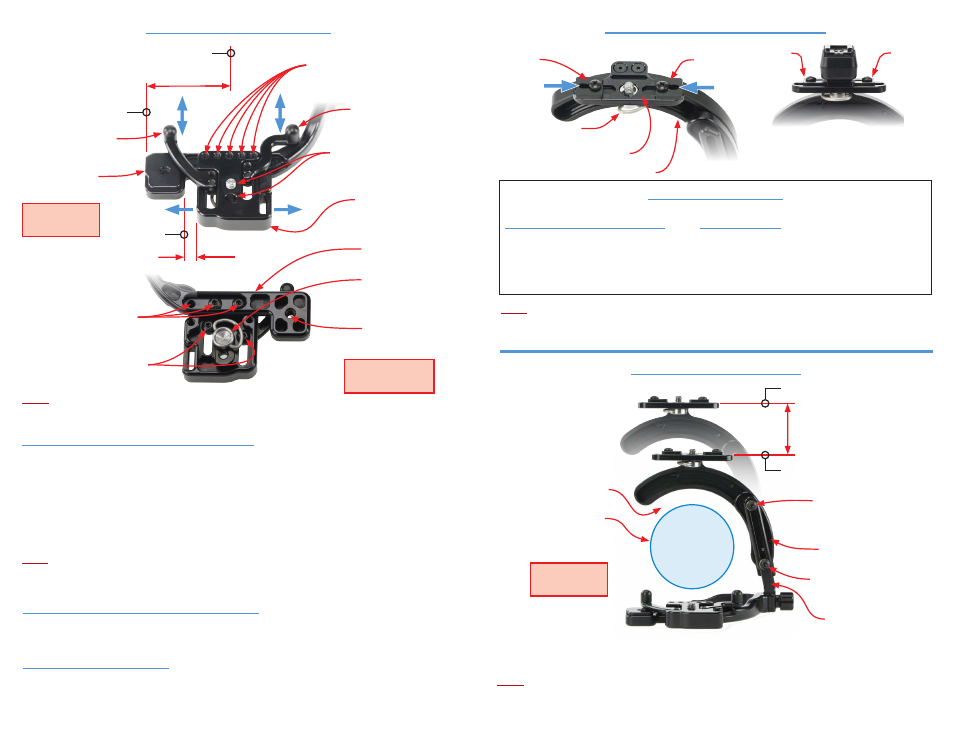
Attaching the camera to the bracket
(2) Setting the camera plate position - Front to Back
The camera plate has two (2) camera screw holes for locating the camera front to back. Attach the camera using
one of the camera screw holes. Position of the camera is a customer preference on how comfortable it feels
when holding the bracket in the horizontal and vertical positions.
(1) Setting the camera plate position - Left to Right
The camera plate has five (5) position holes (5/16” apart) for positioning the camera plate left to right.
Two (2) screws are provided to attach the camera plate to the bracket. Once the correct left to right position has
been determined, use any two support position holes which line up with the camera plate position holes to attach
the camera plate using the 1/8” Allen wrench provided with bracket.
For smaller cameras, or those without add-on vertical grips / battery packs, position the camera plate with a
distance of 5/16” from left position.
For taller cameras, or those with add-on vertical grips / battery packs with the camera mounting hole on center
with the lens, position the camera plate to left position.
Note:
- Prior to attaching the camera, raise the flash rotator to the up position (see: back view of bracket).
- The camera plate has been factory set for small cameras with the camera mounting hole on center of the lens.
Once the camera is positioned properly, adjust the two (2) camera anti-twists to contact the front of the camera.
Tighten the two (2) camera anti-twist screws located on the bottom side of the camera plate using the 1/8” Allen
wrench provided with bracket..
An additional hole in the anti-twist is provided if the camera screw “D” clip interferes with the anti-twist screws.
Note:
Some add-on vertical grips / battery packs have the mounting screw hole off center to the lens. Determine the
correct position to mount the camera plate to the support which locates the center of the lens as close to 1-11/16”
from the end of the support.
(3) Setting the camera anti-twist
Anti-twist
Anti-twist
Shown with Canon
Off Camera cord II attached
Attaching the flash cord to the flash mount
Note:
Do not rotate the flash rotator unless a flash cord or the
RF-FT (mount for wireless flash operation) is attached
to the flash mounting plate and “D” clip of the screw is folded down. Rotating without one of these attached
may cause damage to the rotator and void warranty.
Anti-twist
Anti-twist
Flash rotator
Captive flash screw
“D” clip
Flash mounting plate
1-
2-
3-
4-
Flash anti-twist procedure
Nikon SC-28, SC-29 Cords
(first time installation)
Canon off-camera cord II, Canon Cord 3,
Nikon SC-17 cords (first time installation)
5-
1-
2-
3-
4-
Camera anti-twist
Adjustable front to back
Camera plate position holes (5)
for positioning camera
left to right
Camera position holes (2)
for positioning camera
front to back
5/16”
Left position
1-11/16”
Center of Lens
Camera anti-twist
Adjustable front to back
End of support
Support position holes (3)
for positioning camera
left to right
Camera anti-twist screws (2)
Tripod hole
1/4” x 20 thread
Camera screw
“D” clip stainless steel
1/4” x 20 thread
Top view of
camera plate
Bottom view of
camera plate
Back view of
bracket
Up position
Down position
Upright screw
Up position
(shown for reference)
Upright screw
Down position
Adjusting the flash rotator height
The flash rotator is adjustable to work with short or tall cameras.
Adjust by loosening the upright screw, then position the rotator to be centered around the lens of the camera.
After desired position of rotator is set, lock upright screw using the 1/8” Allen wrench provided with bracket.
Note:
- Rotating without equal space around lens may cause damage to the lens or bracket.
- The leg must be completely folded in or out to rotate flash to avoid damage to the bracket.
Lens outside diameter
Position rotator
for equal space
around lens
Equal space around lens
Attach cord with flash screw
(do not tighten completely)
Slide one anti-twist to cord
(tighten anti-twist screw)
Slide other anti-twist to cord
(tighten anti-twist screw)
Tighten flash screw to cord
Attach cord (reversed) with flash screw
(do not tighten completely)
Slide left anti-twist to cord
(tighten anti-twist screw)
Remove cord and install normal
Slide right anti-twist to cord
(tighten anti-twist screw)
Tighten flash screw to cord
Camera plate
Flash rotator base
Upright
Height Adjustment
Support
Support