CatEye CC-PD100W [Cateye Fit] User Manual
Cateye fit, Preparing the computer, How to install the unit on your bicycle
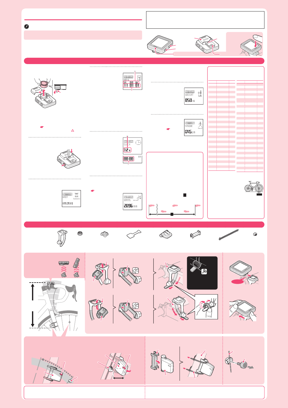
Measure wheel circumference (L) of your bike
To get the most accurate
calibration do a wheel roll out.
With the valve stem perpen-
dicular to the ground, mark
the pavement at the valve
stem. With the riders weight
on the bike, roll the wheel one tire revolution
in a straight line and mark the ground when
the valve stem is perpendicular to the ground
again. Measure the distance in millimeters. This
is the most accurate wheel calibration number.
Before using the computer, please thoroughly read this manual and keep it for future
reference.
Our website shows how to install and set up the unit on your bicycle, in an understandable way
using a movie
(http://www.cateye.com)
.
Installation conditions
The back of the com-
•
puter must face the
speed sensor.
1
Removing the insulation sheet
Remove the battery case cover, and hold
the battery holder tab to pull out the battery.
The battery holder is lifted when either tab
is pulled up. Remove the insulation sheet
under the battery.
If the battery is detached, insert it cor-
*
rectly. (
Replacing the battery
)
Insert the battery holder with the
*
mark
toward the front side of the computer.
2
Press the
AC
button while press-
ing and holding the
MENU
button
(formatting operation)
Check that the
whole screen illu-
mination is turned
on for 5 seconds.
Press and hold the
*
MENU
button for 3
seconds after you release the
AC
button.
3
Select the measurement unit
(Speed, Stride, and Weight)
When the
1.
MODE
button is
pressed, “KM. CM. KG”
and “MILE. INCH. LB”
will fl ash alternatively for
selection.
With the desired measurement unit dis-
2.
played, press the
MENU
button.
4
Set the date
When the
1.
MODE
button
is pressed, “YY/MM/DD”
(Year, Month, Day) will
flash in different order
for selection.
When the
2.
MODE
button is
pressed and held, the item to set will appear
for selection, and “11” (Year) will fl ash.
Press the
3.
MODE
button to increase the
fl ashing value, whereas press and hold it
to switch the item to set. Set “Month” and
“Day” in the same procedure.
Press the
4.
MENU
button to proceed to “Set
the clock”.
When it fails to set the date, “
*
ERROR” will appear.
5
Set the clock
Set the display format of
“12H” or “24H”, and the
values for “Hour” and
“Minute” in the same
procedure as Step
4
.
Press the
MENU
button
to proceed to “Enter the
tire circumference”.
For the display format of “
*
12H”, select
“AM” (morning) or “PM” (afternoon).
6
Enter the tire circumference
Enter the tire circumference of your
bicycle (distance per turn) in mm.
(
Tire circumference reference table
)
Press the
1.
MODE
but-
ton to adjust the value,
and press and hold it to
move to the next digit.
Enter the value for “ones
place digit” through “thousands place digit”
in the same procedure.
Press the
2.
MENU
button to proceed to “Enter
the weight”.
When any invalid value is entered,
*
“ERROR” will appear.
7
Enter the weight
Enter your weight in the
unit you selected in Step
3
(KG or LB).
Set the value in the same
procedure as Step
6
.
Press the
MENU
button to proceed to
“Enter the stride”.
8
Enter the stride
Enter your stride in the
unit you selected (CM
or INCH). (
How to
measure the stride
)
Set the value in the
same procedure as Step
6
.
Press the
MENU
button to confi rm the setting.
Now, preparing the computer is completed.
AC
MENU
SENSOR ZONE
SENSOR ZONE
SENSOR ZONE
SENSOR ZONE
5 mm
5 mm
Nylon ties (x2)
Sensor zone
Speed sensor
Speed sensor
Sensor zone
Magnet
Magnet
Max
70 cm
YES!
Pull
securely
Nylon ties
To the sensor zone
When attaching the bracket to the handlebar
Install the bracket and computer
Package contents
Remove/install the computer
Install the speed sensor
Install the magnet
For receiving sensitivity reasons, attach the bracket so that the back of the computer faces the speed sensor.
*
Use the applicable optional parts when attaching to an aero-shaped handlebar or a large stem.
*
Click
While supporting it by hand,
push it out as if lifting the
front up.
Install it fi rmly in place
until it clicks.
Cut
CAUTION:
Round off the cut edge
of the bracket band to
prevent injury.
ETRTO
Tire size
L (mm)
47-203
12x1.75
935
54-203
12x1.95
940
40-254
14x1.50
1020
47-254
14x1.75
1055
40-305
16x1.50
1185
47-305
16x1.75
1195
54-305
16x2.00
1245
28-349
16x1-1/8
1290
37-349
16x1-3/8
1300
32-369
17x1-1/4 (369)
1340
40-355
18x1.50
1340
47-355
18x1.75
1350
32-406
20x1.25
1450
35-406
20x1.35
1460
40-406
20x1.50
1490
47-406
20x1.75
1515
50-406
20x1.95
1565
28-451
20x1-1/8
1545
37-451
20x1-3/8
1615
37-501
22x1-3/8
1770
40-501
22x1-1/2
1785
47-507
24x1.75
1890
50-507
24x2.00
1925
54-507
24x2.125
1965
25-520
24x1(520)
1753
24x3/4 Tubuler
1785
28-540
24x1-1/8
1795
32-540
24x1-1/4
1905
25-559
26x1(559)
1913
32-559
26x1.25
1950
37-559
26x1.40
2005
40-559
26x1.50
2010
47-559
26x1.75
2023
50-559
26x1.95
2050
54-559
26x2.10
2068
Preparing the computer
Element names
How to install the unit on your bicycle
Stem
Bracket
Bracket
Speed sensor
Sensor rubber pad
Bracket rubber pad
Bracket rubber pad
Remove
backing
Remove
backing
Bracket band
Bracket band
Handlebar
Dial
Right front fork
Spoke
Magnet
Display format
Clock display
Hour/Minute
YY/MM/DD
Bracket band
Bracket
Dial
Speed sensor
Magnet
Bracket rubber pad
Sensor rubber pad
AC
MODE
MODE
MENU
Dot section
Battery
case
cover
The clearance between the speed sensor
•
and magnet is 5 mm or less.
After installing the speed sensor, check that the speed is displayed on the computer by turn-
ing the front wheel with the computer installed to the bracket. If not displayed, review the
installation conditions, and check the positions of the speed sensor and magnet.
CAUTION:
The computer in the bike mode measures speed only when installed on the bracket.
NO!
This unit can be used for measuring speed and distance while installed on your bicycle, and also used
as a pedometer for measuring calorie consumption and number of steps in everyday life while carried
with you all the time. First of all, go through “Preparing the computer” and “How to install the unit on
your bicycle”.
Tire circumference reference table
Generally, the tire size is indicated on the
*
side of the tire.
ETRTO
Tire size
L (mm)
57-559
26x2.125
2070
58-559
26x2.35
2083
75-559
26x3.00
2170
28-590
26x1-1/8
1970
37-590
26x1-3/8
2068
37-584
26x1-1/2
2100
650C Tubuler
26x7/8
1920
20-571
650x20C
1938
23-571
650x23C
1944
25-571
650x25C
26x1(571)
1952
40-590
650x38A
2125
40-584
650x38B
2105
25-630
27x1(630)
2145
28-630
27x1-1/8
2155
32-630
27x1-1/4
2161
37-630
27x1-3/8
2169
18-622
700x18C
2070
19-622
700x19C
2080
20-622
700x20C
2086
23-622 700x23C
2096
25-622
700x25C
2105
28-622
700x28C
2136
30-622
700x30C
2146
32-622
700x32C
2155
700C Tubuler
2130
35-622
700x35C
2168
38-622
700x38C
2180
40-622
700x40C
2200
42-622
700x42C
2224
44-622
700x44C
2235
45-622
700x45C
2242
47-622
700x47C
2268
54-622
29x2.1
2288
60-622
29x2.3
2326
L mm
When attaching the bracket to the stem
Install the speed sensor and magnet
How to measure the stride
The stride means the distance between
adjacent tiptoes of your footprint. Mark at
your tiptoe in the start point and the point
after you make 10 steps, and then measure
the distance between them.
The stride becomes larger as you walk faster.
*
For measurement, walk at a normal speed.
An average stride is determined by dividing the
walking distance by 10 (number of steps).
Walking distance
A
/
10 (Number of steps) = Stride
1
3
2
10
A
Installation conditions
The distance from the speed sensor to the
•
computer must be less than 70 cm.
The magnet must pass through the sensor
•
zone of the speed sensor.
Click
When the computer
is mounted on the
bracket
Battery holder
Insulation sheet
This device complies with Part 15 of the FCC Rules. Operation is subject to the following two condi-
tions:(1)This device may not cause harmful interference, and (2) this device must accept any interfer-
ence received, including interference that may cause undesired operation.
Modifi cations The FCC requires the user to be notifi ed that any changes or modifi cations made to this device
that are not expressly approved by CatEye Co., Ltd. May void the user ’s authority to operate the equipment.
Perform the formatting operation according to the following procedure when you use the unit for the fi rst time or restore the unit to the setting at the time of factory shipment.
CATEYE FIT
CC-PD100W ENG