Airlink SkyIPCam310 User Manual
Page 7
6
3. Internal MIC
The built-in omni-directional microphone allows the camera to receive sound and voice.
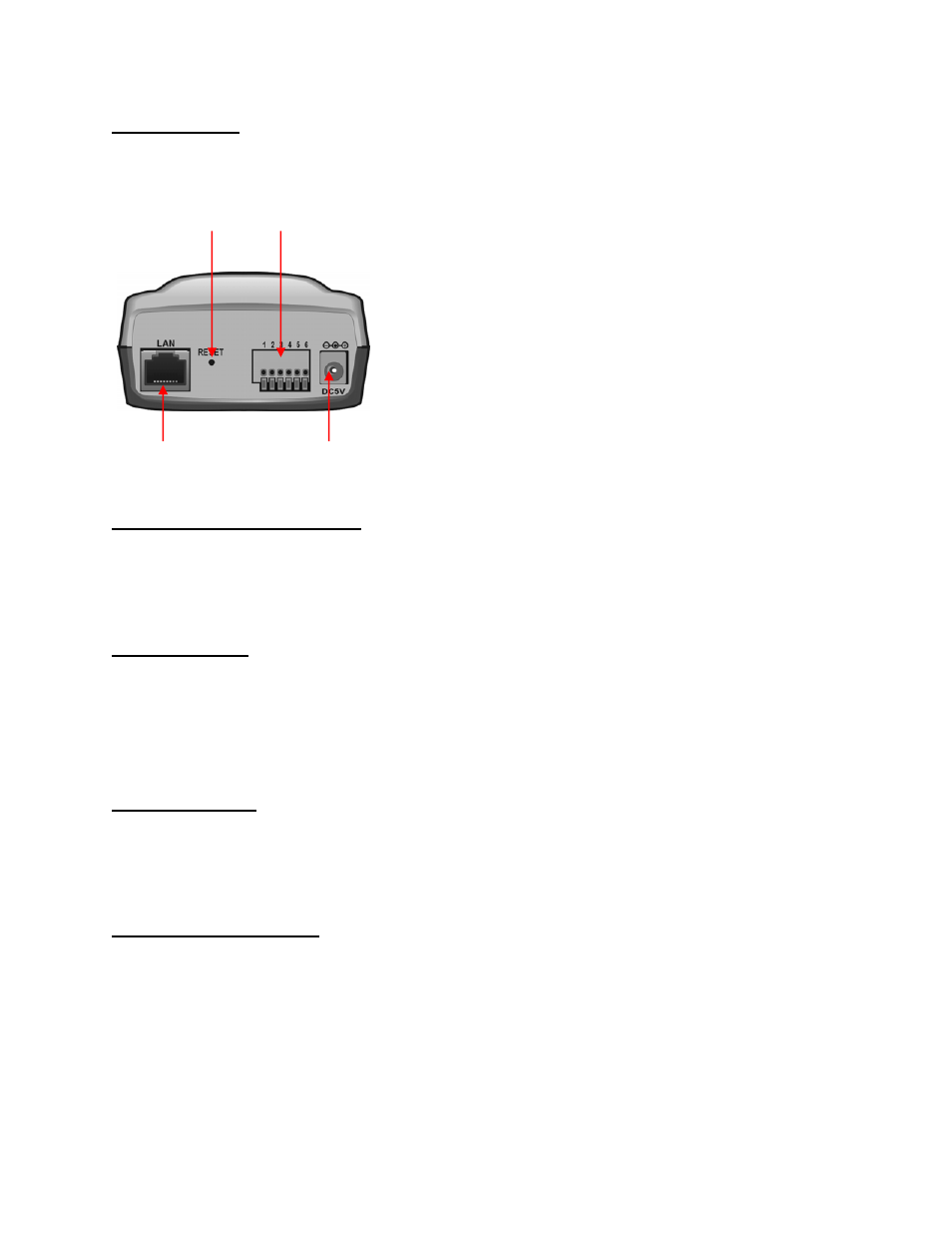
Rear Panel
1. Network Cable Connector
The SkyIPCam310’s rear panel features an RJ-45 connector for connections to 10Base-T
Ethernet cabling or 100Base-TX Fast Ethernet cabling (which should be Category 5 twisted-pair
cable). The port supports the N-Way protocol and “Auto-MDIX” function, allowing the
SkyIPCam310 to automatically detect or negotiate the transmission speed of the network.
2. Reset Button
Reset will be initiated when the reset button is pressed once, and Power LED begins to flash.
Factory Reset will be initiated when the reset button is pressed continuously for three seconds
or when Power LED begins to light up. Release the reset button and the Power LED will begin
to flash, indicating the SkyIPCam310 is changing to factory reset. The IP address will return to
the default setting as 192.168.1.240.
3. I/O Connector
The camera provides the I/O connectors on the rear panel (pin 1/2 are for RS485, pin 3/4 are for
input, pin 5/6 are for output), which provide the physical interface to send and receive digital
signals to a variety of external alarm devices. For more information, refer to 7.4 I/O Terminal
Application.
4. DC Power Connector
The DC power input connector is located on the SkyIPCam310’s rear panel, and is labeled
DC5V with a single jack socket to supply power to the SkyIPCam310. Power will be generated
when the power supply is connected to a wall outlet.
1. Network Cable Connector
4. DC Power Connector
2. Reset Button
3. I/O Connector