Burner/ spark ignition probe, Flow/ return temperature sensors, Flow switch – Atmos Energy INTERCOMBI HE32 User Manual
Page 52: Pressure gauge sensor, Hot water temperature sensor
52
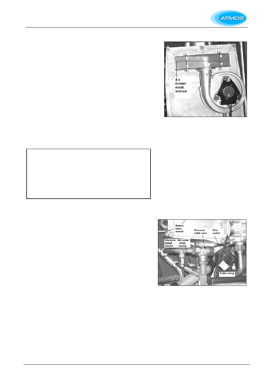
9.2.5 Burner/ spark ignition probe
Remove the front cover of the heat exchanger as described in § 9.1.2.
Unscrew the 4 screws shown on the photo to allow the stainless steel
burner mesh to be removed. These screws are Torx 20 (RVS A2 4,2x25”)
or Allen bolt M4x20 (units before 2006). The burner gasket should be
checked and replaced if damaged. Replace the burner mesh assembly
and refit the screws.
The spark ignition probe is shown in the photo in § 9.1.2 and also the
diagram in § 8.2. To replace the probe, pull off the ignition cable and
unscrew the 2 screws (Allen bolt M4x8). The seal should be checked and
replaced if damaged. Replace the probe and refit the seal and the screws.
Check the spark gap and replace the front cover, as described in § 9.1.2.
9.2.6 Flow/ return temperature sensors
The supply temp. sensor is located above the return temp. sensor. The
latter is shown in the photo. Disconnect the two pin connector and release
the spring clip. Pull out the sensor and replace.
Note: The replacement of the components below this box
requires the appliance to be drained:-
CH side – Drain the appliance using the drain tap and drain the
system at the lowest point.
HW side – Close the valve for the cold water into the appliance
and drain by disconnecting the HW connections underneath the
appliance or opening hot water taps.
After replacement, refill the appliance as given in § 6.1.
9.2.7 Flow switch
Disconnect the two pin connector and undo the two unions to release
the flow switch. Ensure that the two sealing rings and brass ring are
not damaged and are replaced with the new flow switch.
Note: When replacing with new device, ensure arrow for flow on the
black body is pointing vertically upwards.
9.2.8 Pressure relief valve
Remove the plastic pipe from the safety discharge. Undo the pressure
sensor capillary and undo the union at the connection with the CH flow
pipe. Remove the pressure relief valve and inlet pipe. Remove the
plastic fitting from the discharge and undo the pipe connection to allow
removal of the valve. Fit replacement valve in reverse order using a
sealant suitable for potable water.
9.2.9 Pressure gauge sensor
Undo the pressure sensor capillary and unscrew the two posidrive
screws to release the cable clamp. Remove the gauge and capillary,
and replace.
9.2.10 Hot water temperature sensor
Remove the electrical connector. Undo the sensor with its ‘O’ ring and
replace.