Positions 1-4: carrier signal enable/disable, Position 5: rs-232/pctouch mode, Positions 6-8: baud rate setting – AMX Interface Port AXB-IRS4 User Manual
Page 8
Configuration and Installation
4
AXB-IRS4 IR/Serial Interface (4 Ports)
Positions 1-4: Carrier signal enable/disable
DIP Switch positions 1-4 on the
CARRIER/BAUD
DIP switch determine wether the AXB-IRS4
transmits carrier signals along with the IR equipment codes.
!
If DIP switch positions 1 through 4 are set to the up position, the carrier signal is enabled
and the AXB-IRS4 transmits IR equipment codes at device-specific signal frequencies.
!
If DIP switch positions 1 through 4 are set to NC (down), the carrier signal is disabled
and the IR equipment codes transmit without the carrier signal.
Set the DIP switch positions 1 through 4 when you determine the port assignments and signal
requirements for the IR and serial devices in your system.
Position 5: RS-232/PCTouch mode
DIP switch position 5 on the
CARRIER/BAUD
DIP switch sets either RS-232 or PCTouch mode. If
you enable PCTouch mode, the AXB-IRS4 will only respond to PCTouch (PCCOM) command
protocol. If you enable RS-232 mode, the AXB-IRS4 will respond to the standard AXB-IRS4
control protocol, PCCOM control protocol, and SX-DCU+ control protocol. You can also use RS-
232 mode to download codes to the AXB-IRS4 with the IRLIB software program.
!
Position 5 (up): RS-232 mode enabled.
!
Position 5 (down): PCTouch mode enabled.
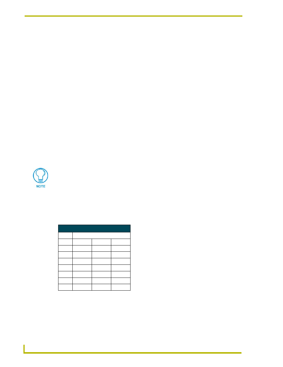
Positions 6-8: Baud rate setting
DIP switch positions 6-8 on the
CARRIER/BAUD
DIP switch sets the baud rate for RS232
communications. Communication settings are 1 stop bit, 8 data bits, and no parity. The following
table shows the baud rate settings on the
CARRIER/BAUD
DIP switch.
Refer to the PCTouch/ PCDesign Instruction Manual for detailed PCTouch program
information.
RS-232 Baud Rate Settings
Baud
DIP Switches
Rates
6
7
8
300
Off
Off
Off
600
On
Off
Off
1,200
Off
On
Off
2,400
On
On
Off
4,800
Off
Off
On
9,600
On
Off
On
19,200
Off
On
On