AMX Interface Port AXB-IRS4 User Manual
Page 12
Configuration and Installation
8
AXB-IRS4 IR/Serial Interface (4 Ports)
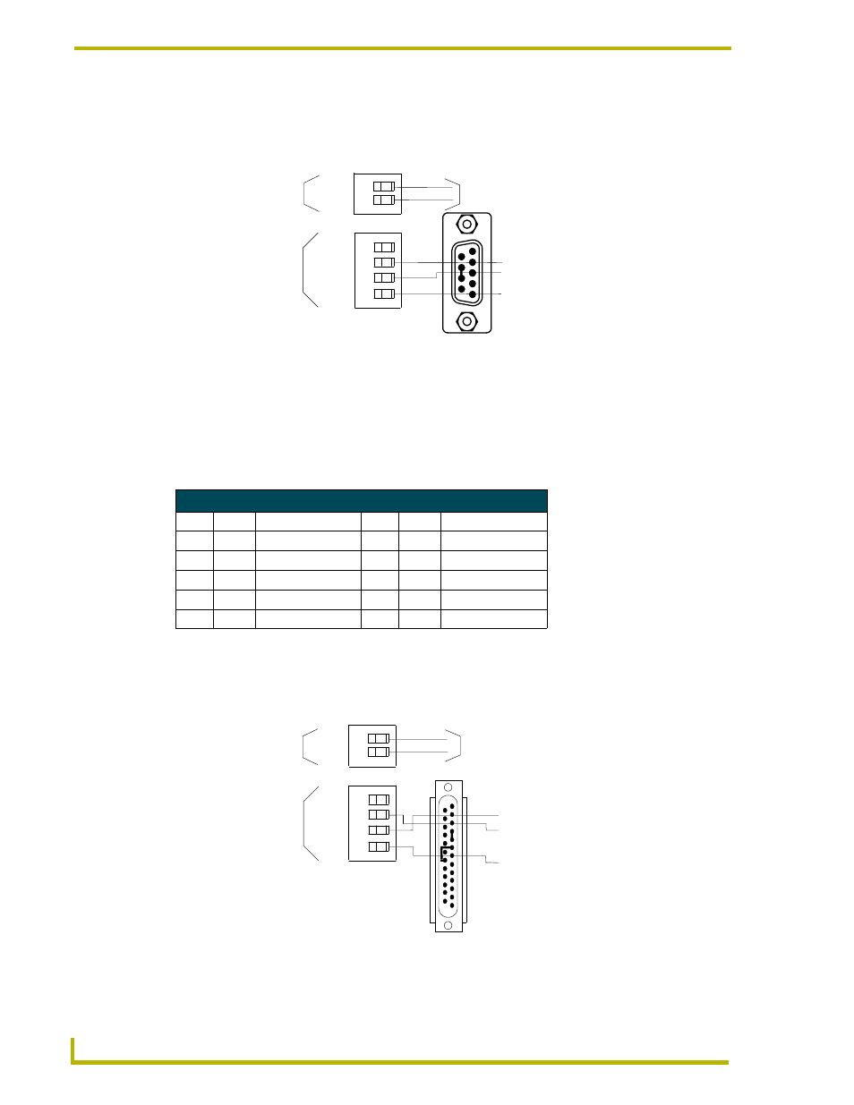
FIG. 8 shows the AXlink/RS-232, DB-9, and power supply wiring diagram. For some applications,
you may need to strap pins 7 (request to send) and 8 (clear to send) together depending on the PC
(as shown in the illustration).
Using the AXlink-to-DB-25 connector cable for a PC system
The AXlink/RS-232 connector on the back of the AXB-IRS4 can be connected to a PC-based
system with a DB-25 connector cable. Connector pins 2, 3, and 7 are used for data and ground.
Refer to the following table for the DB-25 wiring pinouts.
FIG. 9 shows the AXlink/RS-232, DB-25, and power supply wiring diagram. For some
applications, you may need to strap pin 4 (ready to send) to 5 (clear to send) and/or pin 6 (data set
ready) to 20 (data terminal ready) depending on the PC.
FIG. 8 AXlink/RS-232, DB-9, and power supply wiring diagram
DB-25 Wiring Pinouts
Pin
Signal Function
Pin
Signal Function
1
N/A
Not used
6
DSR
Data set ready
2
TXD
Transmit data
7
GND
Signal ground
3
RXD
Receive data
8-19
N/A
Not used
4
RTS
Ready to send
20
DTR
Data terminal ready
5
CTS
Clear to send
21-25
N/A
Not used
FIG. 9 AXlink/RS-232, DB-25, and power supply wiring diagram
PWR (+)
GND (-)
PWR(+)
AXM/RX
AXP/TX
GND (-)
5 (GND)
2 (RXD)
3 (TXD)
12 VDC PWR connector
on AXB-CAM
AXlink/RS232 connector
on AXB-CAM
12 VDC power supply
DB-9 connector (male)
PWR (+)
GND (-)
PWR(+)
AXM/RX
AXP/TX
GND (-)
7 (GND)
2 (TXD)
3 (RXD)
12 VDC PWR connector
on AXB-CAM
AXlink/RS232 connector
on AXB-CAM
12 VDC power supply
DB-25 connector (male)