Acer 1800 User Manual
Page 37
Chapter 1
29
NOTE:
*1. The display can not happen flicker or shutdown.
*2. Limited lamp maximum current by DAC_BRIC signal:
DAC_BRIG signal comes from system with internal resistance of 3K .
When add 1V DAC, the 100% Lamp current will decrease 0.5mA.
*3. Inverter operating frequency should be within specification (50~70kHz) at max. and min.
brightness load.
*4. INV_PWM enable implies INV_PWM signal is High level (On duty cycle is 100%). It is a square
wave of 150Hz to adjust backlight brightness that is a function of PWM duty cycle. Backlight
brightness is maximum value under INV_PWM at 100% and brightness is minimum under
INV_PWM at 40%.
*5.The system interface signals belong to 3.3V.
*6. Please make sure open lamp output voltage should be within starting voltage specification.
*7. Inverter should pass human body safety test.
*8. Inverter should be no smoking by any component open/short test.
*9. Transformer voltage stress should not be over 85% under any condition.
(turn on overshoot transient and line transient.)
*10. Inverter should without acoustic at 10cm distance..
Thermal
All components on inverter board should follow below rules:
1. Component using conditions (component stress) must be within component specification including voltage
rating, current rating, temperature etc.
2. Component temperature should follow below:
T
∆T <=40 C, at 25 C and without airflow.
T
Component temperature can’t the Bezel deformed of system.
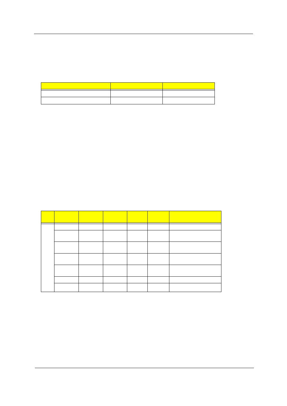
Lamp limited current
DAC_BRIG
INV_PWM
Max.
0V
100%
Min.
3.3V
100%
Electrical specification
No
.
Symbol
Min.
Typ.
Max.
Unit
Comment
1
V oper*
--
785
--
Vrms
Lamp operating voltage
IL
6.2
6.5
6.8
mArms
DAC_BRIG: 0 V, PWM:
100%
IL
3.3
3.6
3.9
mArms
DAC_BRIG: 0 V,
PWM:40%
IL
5.7
6.0
6.3
mArms
DAC_BRIG: 0.5V,
PWM:100%
IL
3
3.3
3.6
mArms
DAC_BRIG: 0.5V,
PWM:40%
f
50
60
70
kHz
76%
--
--
--
Ω
η
°
°