Bottom view – Acer 5540 User Manual
Page 94
88
Chapter 5
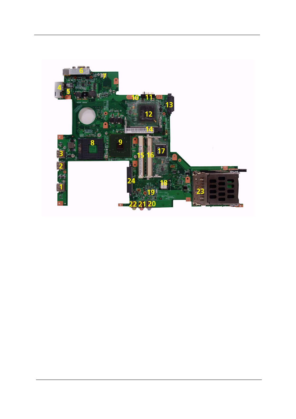
Bottom View
NOTE: This is engineering sample. The image above may not be exactly the same as the real main board you
get.
1
USB2
USB port
13
ODD1
ODD Connector
2
USB3
USB port
14
WIN1
Wireless LAN Card Slotr
3
USB4
USB port
15
DM1
DIMM Slot1
4
LAN1
RJ11+RJ45 (Modem Port+ Ethernet
Port)
16
DM3
DIMM Slot2
5
MDCW
1
Modem Cable Connector
17
U44
Keyboard Controller (RE144B)
6
CRT1
External Display Port
18
U49
BIOS ROM
7
MDC
Modem Board Connector
19
U32
Audio Codec (Realtek ACL883)
8
U41
CPU Socket
20
LIN1
Line-in Jack
9
U38
North Bridge ()
21
MIC2
Headphones/Speakers/Line-Out Jack
10
FAN1
System Fan Cable Connector
22
LOUT1
Line-in Jack
11
BAT1
Battery Connector
23
PC1
PC Card Slot
12
South Bridge (ICH7M)
24
HDD1
HDD Connector
This manual is related to the following products: