Asus AP130-E1 User Manual
Page 54
Chapter 2: Hardware setup
2-38
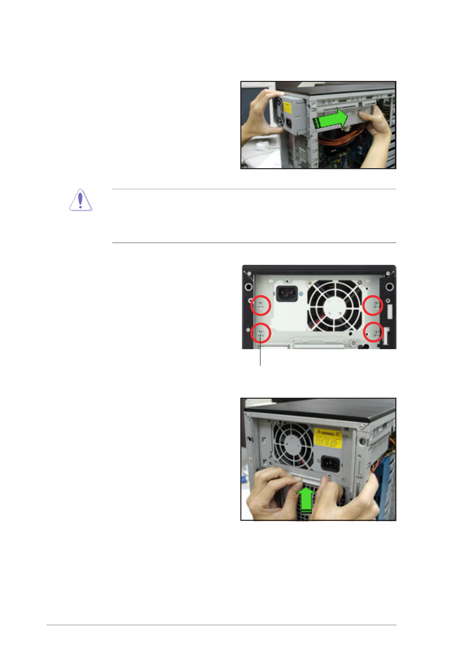
To install a power supply module:
1. Firmly hold the power supply
module and insert it into the
power supply cage.
2. Push the power supply all the way
in until its outer end aligns with
the rear panel.
Be careful with the power supply cables when inserting the power
supply module into the cage. Due to space constraints, the cables may
get entangled with the installed components or other cables, causing
the cables to break!
3. Place the metal plate flat on the
outer end of the power supply
module, flushed to the top of the
chassis, while matching the four
hooks with their corresponding
holes on the rear panel.
Hook matched to a hole
4. Hold the metal plate bar and push
it upward to lock the hooks to
their holes. At the same time, you
may also push the top of the
metal plate to fit it completely.
5. Secure the metal plate with the
thumb screw.
- CG8565 (410 pages)
- CG8565 (246 pages)
- CS5111 (26 pages)
- CS5120 (1 page)
- ET1611PUK (38 pages)
- S2-P8H61E (80 pages)
- P2-PH1 (80 pages)
- P1-P5945G (80 pages)
- P2-P5945GCX (90 pages)
- CG8270 (218 pages)
- CG8270 (536 pages)
- CG8270 (72 pages)
- CG8270 (76 pages)
- CG8270 (534 pages)
- CG8270 (362 pages)
- P3-P5G31 (100 pages)
- P3-PH4 (80 pages)
- P2-M2A690G (80 pages)
- P2-M2A690G (8 pages)
- P4-P5N9300 (1 page)
- P4-P5N9300 (82 pages)
- P1-P5945GC (92 pages)
- P2-P5945GC (92 pages)
- P3-P5G33 (98 pages)
- T3-P5945GC (80 pages)
- T3-P5945GCX (80 pages)
- P2-M2A690G (94 pages)
- T3-PH1 (80 pages)
- T3-PH1 (82 pages)
- T5-P5G41E (82 pages)
- T5-P5G41E (76 pages)
- S1-AT5NM10E (68 pages)
- P6-P7H55E (67 pages)
- ES5000 (174 pages)
- T4-P5G43 (104 pages)
- T-P5G31 (92 pages)
- BT6130 (60 pages)
- BT6130 (54 pages)
- BT6130 (2 pages)
- CG8265 (350 pages)
- CG8265 (210 pages)
- CM1740 (330 pages)
- CM1740 (70 pages)
- CM1740 (198 pages)
- P6-M4A3000E (59 pages)