System setup, Chapter – elektraLite CP16/24 User Manual
Page 4
3
SYSTEM SETUP
After unpacking the CP16/24, plug in the external power supply and turn on the power switch on the front
panel. The display should light up and display the product name along with the current software revision. If the
display does not light up consult the troubleshooting chapter in this manual.
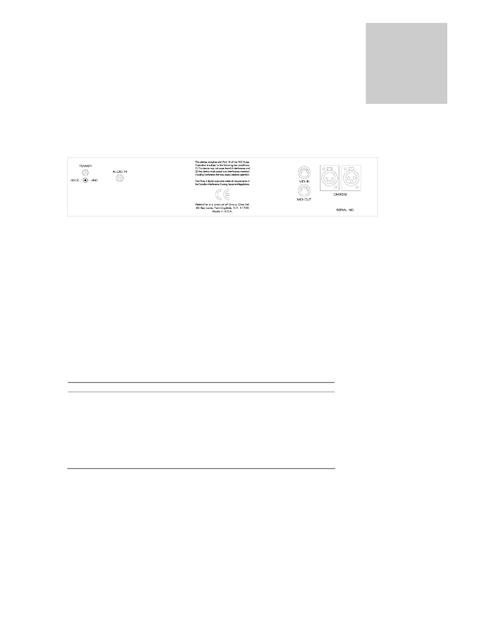
CP16/24 Rear Panel
DMX512
The moving light fixtures are connected to the CP16/24 via the DMX512 jacks on the rear panel. A standard 5
pin jack and a 3 pin jack is provided. The two jacks are wired in parallel with pin 1 to ground, pin 2 to data
minus and pin 3 to data plus.
The CP16/24 is designed to control a variety of fixture types which accept up to 24 channels of control per
fixture. The CP16/24 outputs 384 DMX512 channels. You can connect more than 16 fixtures but some will
have to share channels and will operate in unison. The default starting addresses for the 16 fixtures are set at 24
channel intervals and are shown below, consult your particular fixture's instructions on how to set the starting
channel address on the fixture. There is a soft patch feature in the CP16/24, which also allows you to change
these starting addresses.
Fixture
Start Address
Fixture
Start Address
1 001
9
193
2 025
10
217
3 049
11
241
4 073
12
265
5 097
13
289
6 121
14
313
7 145
15
337
8 169
16
361
After the fixtures are connected and the start addresses set you must next tell the CP16/24 what type of fixture
is connected at a particular address by making a selection from the fixture library. Consult the "System
Programming" chapter of this manual for further instructions.
.
Chapter
2