ADTRAN D4 U-BR1TE V User Manual
Page 6
6
Section 61104020L4-5, Issue 3
61104020L4-5C
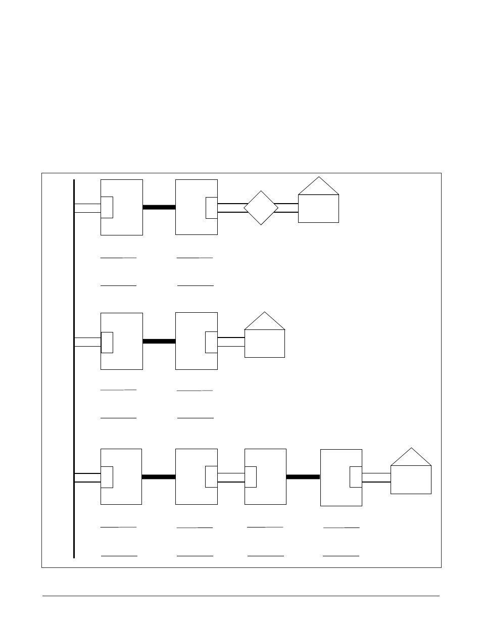
Figure 6 displays the position switch settings at
network locations.
Front Panel Features
The U-BR1TE V front panel features a two position
DIP switch, a recessed pushbutton, a rotary switch, a
bantam jack, and LEDs, as illustrated in Figure 1.
The B1/B2 DIP Switch selects the desired bearer
channel, B1 or B2, to be tested during local tests
using the U-BR1TE V front panel.
The NORM/PTRN DIP Switch is recessed to prevent
inadvertent operation. The ten-position rotary switch
is used to determine the specific test that will be
performed, including downstream loopbacks
(see Table 2).
LED indicators display current status of the unit, as
listed in Table 3.
Figure 6. Position Switch Settings at Network Locations for ISDN Applications
2-Wire
2-Wire
T1
2-Wire
2-Wire
T1
2-Wire
T1
2-Wire
2-Wire
T1
ISDN
Switch
D4
Channel
Bank
Customer
NT1
D4/SLC-96
RT
Channel
Bank
Adjacent to
Switch
Tandem Office
(Source)
Tandem Office (Sink)
Adjacent to Customer
D4
Channel
Bank
D4/SLC-96
COT
Channel
Bank
L
U
L
T
L
U
L
T
L
U
N
T
L
U
N
T
D4/SLC- 96
COT
Channel
Bank
D4/SLC-96
RT
Channel
Bank
Adjacent to
Switch
Adjacent to
Customer
Adjacent to
Switch
Adjacent to
Customer
L
U
L
T
L
U
N
T
Customer
NT1
Note:
Refer to Table 1 for switch
function descriptions.
D4/SLC-96
COT
Channel
Bank
D4/SLC-96
RT
Channel
Bank
L
U
L
T
L
U
N
T
2-Wire
Loop
Customer
NT1
ISDN
RP
SW3
1 - LUNT (COT)
2 - ADJ
SW3
1 - LULT (RT)
2 - ADJ
SW3
1 - LUNT (COT)
2 - ADJ
SW3
1 - LULT (RT)
2 - ADJ
SW3
1 - LUNT (COT)
2 - ADJ
SW3
1 - LULT (RT)
2 - TANDEM
SW3
1 - LUNT (COT)
2 - TANDEM
SW3
1 - LULT (RT)
2 - ADJ
SW6
Norm
SW6
Power
SW6
Norm
SW6
Norm
SW6
Norm
SW6
Norm
SW6
Norm
SW6
Norm