ADTRAN D4 U-BR1TE V User Manual
Page 10
10
Section 61104020L4-5, Issue 3
61104020L4-5C
IDSL/DDS Description
The U-BR1TE V may be deployed in the adjacent to
customer position to provide transport for DDS/Frame
Relay services with an ADTRAN IDSL OCU-R. This
allows pair savings over traditional DDS deployment
on local loops up to 18 kft of mixed gauge wire. The
IDSL OCU-R is used to terminate the U-interface at
the customer’s premises provided by the U-BR1TE V
and to convert the 2-wire ISDN signal to a 4-wire
AMI DDS signal for presentation to the customer.
Together, the U-BR1TE V and IDSL OCU-R allow
testing over the ISDN transport network to be
performed with traditional DDS methods. In this
mode U-BR1TE Vs may be placed in tandem and
function as DS0 DPs while the IDSL OCU-R
functions as an OCU. See Figure 7 for various
U-BR1TE V DDS arrangements.
DDS Testing
For leased mode or DDS applications with the
U-BR1TE V the D channel is typically disabled.
Without the D channel, standard ISDN EOC
loopbacks are unavailable to the ISDN transport
system and testing may only be accomplished by
using the in-band DDS loopback commands. The
U-BR1TE V responds to latching loopback sequences
for the DS0 DP. The U-BR1TE V allows the OCU
loopback command to pass in-band downstream to the
IDSL OCU-R.
Upon receipt of a DS0 DP latching loopback sequence
the U-BR1TE V initiates a bilateral loopback for the
B1 channel. This bilateral loopback allows testing of
the 2B1Q local loop to the IDSL OCU-R
simultaneously with network testing to the U-BR1TE
V.
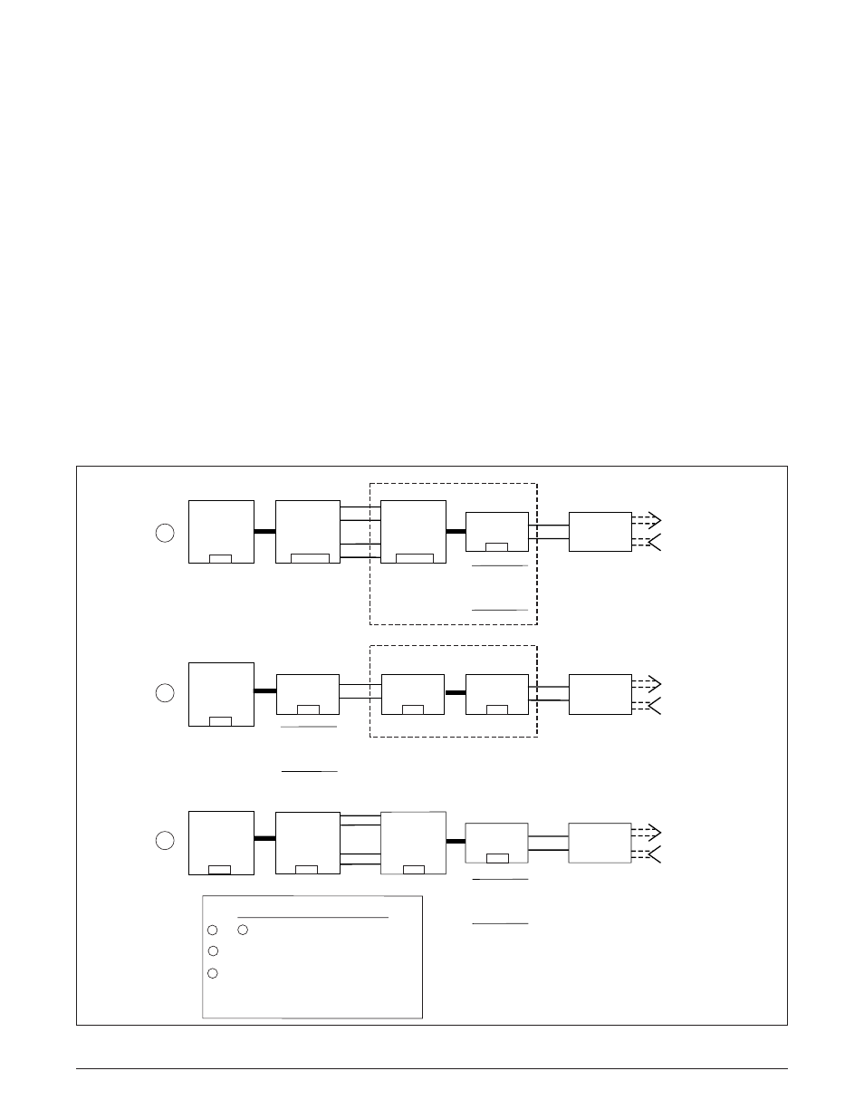
Figure 7. U-BR1TE V IDSL/DDS Circuit Diagram
4W DS0 DP
or
OCU
T1
T1
D4
A
B
C
D
E
D4/DCS
COT/DCS
RT
4W DS0 DP
or
DCS
4W DS0 DP
or
DCS
2-Wire
Local
Loop
2-Wire
Local
Loop
2-Wire
Local
Loop
4W
Digital
4W
Digital
U-BR1TE
1B
SLC 96
IDSL OCU-R
1
4W DS0 DP
or
OCU
T1
T1
D4
A
B
C
D
E
D4
D4
D4
4W DS0 DP
or
DCS
IDSL OCU-R
Customer
Premises
Customer
Premises
Customer
Premises
4W DS0 DP
or
OCU
T1
T1
D4
A
B
C
D
E
COT
RT
U-BR1TE
1B
U-BR1TE
1B+D
2W
Digital
U-BR1TE
1B+D
U-BR1TE
1B
Non-ADTRAN U-BR1TE 1B+D
IDSL OCU-R
2
3
4W DS0 DP
or
DCS
D4
SW3
1 - LULT (RT)
2 - TANDEM
SW6
SW3
1 - LULT (RT)
2 - ADJ
SW6
Equipment Requirements
D & 3 D: Must be 1104020L4 w/ power enabled
B: Must be 1104020L4 w/ Power Disabled
E: Requires local AC power
1
2
2
NOTE: Refer to Table 1 for DIP switch function
descriptions.
Normal
Power
SW3
1 - LULT (RT)
2 - ADJ
SW6
Power