Hardware setup, 1 motherboard layout, Motherboard layout 3. h/w setup – Asus A7N266-E User Manual
Page 14: Socket 462, Nvidia
14
ASUS A7N266-E User’s Manual
3. HARDWARE SETUP
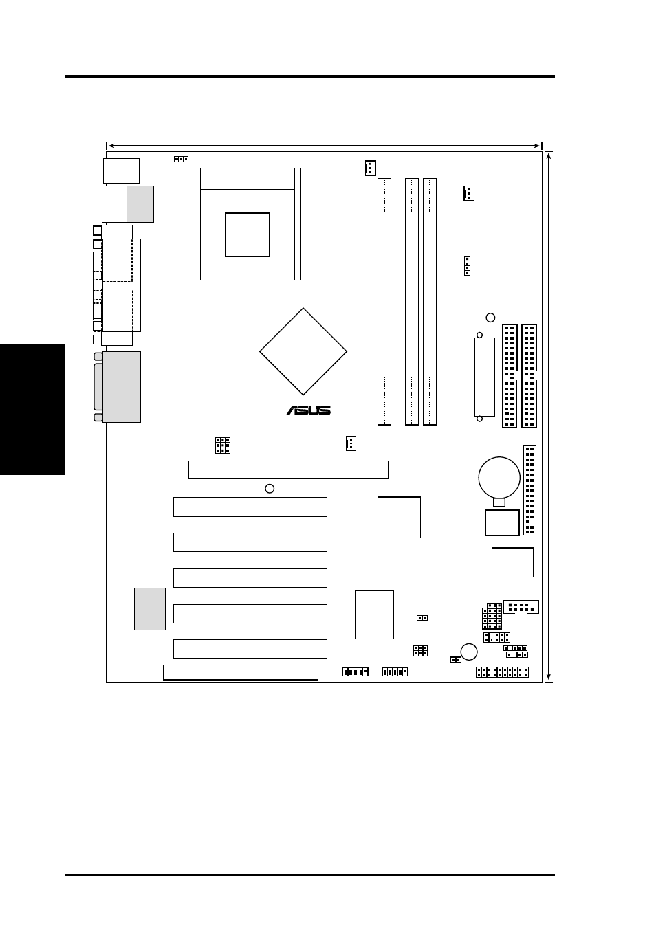
3.1 Motherboard Layout
Motherboard Layout
3. H/W SETUP
IR
24.5cm (9.64in)
30.5cm (12.0in)
Primary IDE
Secondary IDE
FLOPPY
A7N266-E
nVidia
MCP-D
Chipset
ASUS
ASIC
with Hardware
Monitor
Accelerated Graphics Port (AGP Pro)
nVidia
nForce
IGP-128
Chipset
CR2032 3V
Lithium Cell
CMOS Power
PLED
0
1
DDR DIMM1 (64/72 bit, 184-pin module)
0 1
0
1
DDR DIMM2 (64/72 bit, 184-pin module)
2 3
A
TX Power Connector
ACR
Super
I/O
2Mb
BIOS
0
1
DDR DIMM2 (64/72 bit, 184-pin module)
4 5
®
Socket 462
PCI 1
PCI 2
PCI 3
PCI 4
PCI 5
PS/2
T: Mouse
B: Keyboard
RJ-45
Top:
USB1
USB2
Bottom:
COM1
P
ARALLEL
POR
T
VGA
GAME_AUDIO
Realtek
R
TL8100
COM2
VDDR
PANEL
USB45
USB23
JTPWR
USBPWR01
SMB
CHASSIS
BUZZER
IDELED
USBPWR23
USBPWR45
CLRTC
BSEL0
CPU_FAN
CHA_FAN
NB_FAN
VID1
VID2
VID3
VID4
BSEL1
WARNING
JEN
(Grayed components are optional at the time of purchase.)
- Xonar DX (80 pages)
- Xonar DX (10 pages)
- PCI Express Audio Card Xonar DX (70 pages)
- Audio Card Xonar D2X (70 pages)
- Xonar D2X (88 pages)
- Xonar D2X (84 pages)
- D2X (88 pages)
- ROG Xonar Phoebus (72 pages)
- ROG Xonar Phoebus (122 pages)
- Xonar DSX (26 pages)
- Xonar DSX (29 pages)
- Xonar DGX (58 pages)
- Xonar DGX (38 pages)
- Xonar DGX (33 pages)
- Xonar DG (54 pages)
- Xonar DG (58 pages)
- Xonar DG (32 pages)
- Xonar DG (28 pages)
- Xonar Essence ST (35 pages)
- Xonar Essence ST (40 pages)
- Xonar Essence ST (53 pages)
- Xonar Essence ST (52 pages)
- Xonar DS (54 pages)
- Xonar DS (33 pages)
- Xonar Xense (47 pages)
- Xonar Xense (70 pages)
- Xonar Xense (45 pages)
- Xonar U3 (56 pages)
- Xonar U3 (38 pages)
- Xonar Essence STX (49 pages)
- Xonar Essence STX (10 pages)
- Xonar Essence STX (32 pages)
- XONAR D1 E4009 (72 pages)
- Xonar D1 (72 pages)
- Xonar D1 (80 pages)
- Xonar D1 (10 pages)
- Xonar Essence One (7 pages)
- Xonar Essence One (5 pages)
- Xonar HDAV 1.3 (100 pages)
- Motherboard M4A78-EM (64 pages)
- A7N8X-VM/400 (64 pages)
- K8V-XE (86 pages)
- K8V-XE (20 pages)
- M2R32-MVP (160 pages)
- M2R32-MVP (60 pages)