Spektrum SPMAR12200 User Manual
Page 18
EN
18
Advanced Range Testing Using Flight Log Data
The Standard Range Testing procedure is
recommended for most sport aircraft. For
sophisticated aircraft that contain significant
amounts of conductive materials (e.g. turbine
powered jets, some types of scale aircraft,
aircraft with carbon fuselages, etc.), the
following advanced range check will confirm
that all remote receivers are operating optimally and that the installation (position
of the receivers) is optimized for the specific aircraft. This Advanced Range Check
allows the RF performance of each remote receiver to be evaluated and to optimize
the locations of each individual remote receiver.
Advanced Range Testing
1. To view the flight log data on the screen, press and release the I and II buttons
together while at the main screen and the flight log data will appear.
2. Have a helper hold your aircraft while observing the Flight Log data.
3. Standing 30 paces away from the model, face the model with the transmitter in
your normal flying position and put your transmitter into range test mode. This
causes reduced power output from the transmitter.
4. Have your helper position the model in various orientations (nose up, nose down,
nose toward the transmitter, nose away from the transmitter, etc.) while your
helper watches the Flight Log, noting any correlation between the aircraft’s
orientation and frame losses. Do this for 1 minute. The timer on the transmitter
can be used here. For giant-scale aircraft, it’s recommended that the airplane be
tipped up on its nose and rotated 360 degrees for one minute while recording
the data. Next, place the airplane on its wheels and do a second test, rotating the
aircraft in all directions for one minute.
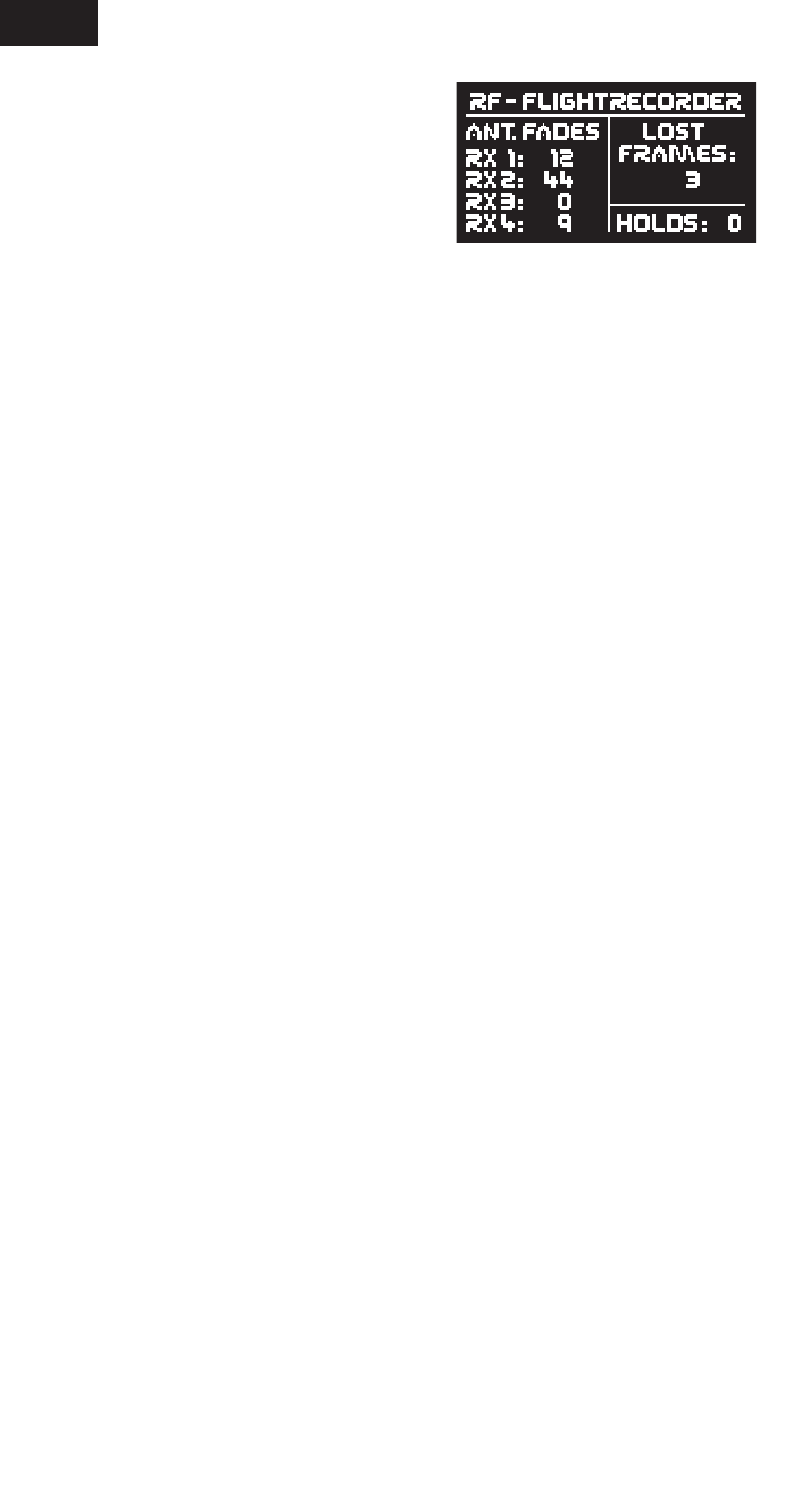
5. After one minute, a successful range check will have less than ten recorded
frame losses. Scrolling the Flight Log through the antenna fades (RX1, RX2, RX3,
and RX4) allows you to evaluate the performance of each receiver. Antenna fades
should be relatively uniform. If a specific antenna is experiencing a high degree of
fades, then that antenna should be moved to a different location.
6. A successful advanced test will yield the following:
H: 0 holds
F: less than 10 frame losses
RX1, RX2, RX3, RX4: Frame losses will typically be less than 100. It’s
important to compare the relative frame losses. If a particular receiver has a
significantly higher frame loss value (2 to 3X) then the test should be redone. If
the same results occur, move the offending receiver to a different location.
Antenna fades: Represents the loss of a bit of information on that specific
antenna. Typically, it’s normal to have as many as 50 to 100 antenna fades during
a flight. If any single antenna experiences over 500 fades in a single flight, the
antenna should be repositioned in the aircraft to optimize the RF link.
Frame loss: Represents simultaneous antenna fades on all attached receivers. If
the RF link is performing optimally, frame losses per flight should be less than 20.
The antenna fades that caused the frame loss are recorded and will be added to
the total antenna fades.
A
Hold occurs when 45 consecutive frame losses occur. This takes about one
second. If a hold occurs during a flight, it’s important to re-evaluate the system,
moving the antennas to different locations and/or checking to be sure the
transmitter and receivers are all working correctly. The frame losses that led to
the hold are not added to the total frame losses.
NOTICE: The Flight Log data is reset to 0 when you exit this screen display. It is not
possible to read out previous data again.