Quick install guide 5, Slide the uplink module into place, Apply ac power to the switch unit – Allied Telesis Uplink Module User Manual
Page 5: Connect the data cables, Check the uplink module’s leds, Card guide
Quick Install Guide
5
C613-04022-01 REV D
7.
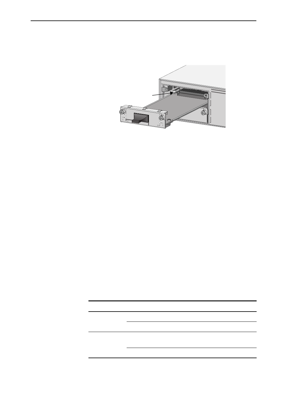
Slide the Uplink Module into place.
Make sure that the module is aligned with the card guides on each side of
the bay (see Figure 2).
Figure 2: Installing an Uplink Module.
8.
Secure the Uplink Module to the switch unit.
Firmly press the Uplink Module until its connectors engage the uplink bay
connectors inside the switch unit.
Use a screwdriver to tighten the Uplink Module’s screws. Do not
over-tighten the screws.
9.
Apply AC power to the switch unit.
Plug the power cord into the switch unit’s rear panel. The switch’s Fault
LED should flash for approximately 10 seconds as it runs internal tests.
10. If you disconnected a redundant power supply in step 3, reconnect it.
11. Check that the Power LED on the switch unit’s front panel lights green.
If the LED fails to light, refer to the Troubleshooting section of the Uplink
Module Hardware Reference.
12. Connect the data cables.
If fitted, remove the Uplink Module’s port dust cover and connect the data
cable. Make sure that each cable connection is secure.
13. Check the Uplink Module’s LEDs.
Table 1 and Table 2 outline the Uplink Module LEDs. Information on
Switch System and Switch Port LEDs can be found in the Troubleshooting
section of the Hardware Reference for your switch unit.
Table: 1 Uplink Module LEDs (AT-A35/SX and AT-A35/LX)
LED
State
Function
Link
Green
The port is receiving light
Off
No link is present
Activity
Flashing Amber
Frames are being transmitted or received
through the port
Off
No activity is occurring
A
B
AT-A35/SX
1000BASE-FX
/SC
RX
TX
LINK
ACTIVITY
FULL DUP
HALF DUP
COL
LINK
ACTIVITY
FULL DUP
HALF DUP
COL
COL
Card Guide