Allied Telesis Uplink Module User Manual
Page 4
4
Uplink Module
C613-04022-01 REV D
2.
Gather the tools and equipment you will need.
A medium-sized flat-bladed screwdriver may be useful when loosening
the Uplink Module thumb screws.
You should also have any cables required for connecting the Uplink
Module to other network devices.
3.
If connected, disconnect the switch unit from the redundant power supply.
4.
Disconnect the switch unit from the mains power supply.
Be sure to disconnect the power cord and the redundant power supply cable
before installing an Uplink Module. Installing an Uplink Module with the
switch unit powered ON can damage the Uplink Module.
The power cord and the redundant power supply cable are used to disconnect
the switch unit. To de-energise the equipment, disconnect the power cord and
the redundant power supply cable.
5.
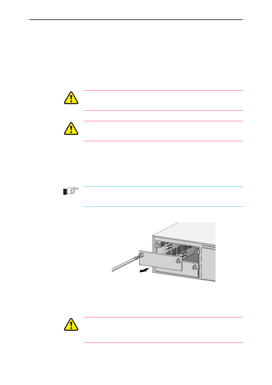
Remove the appropriate uplink bay face-plate on the switch unit’s front panel.
AR800 Series Modular Switching Routers and Rapier Switches have two
uplink module expansion bays. If this is the first Uplink Module to be
installed, to simplify VLAN configuration, it should be installed in the top
bay. Remove the face-plate as shown in Figure 1.
Keep the face-plate for future use. If you should remove the Uplink Module, replace the
face-plate to prevent dust and debris from entering the switch unit and to maintain
proper airflow.
Figure 1: Removing a blank face-plate.
6.
Prepare the Uplink Module.
In an antistatic environment, remove the Uplink Module from its packing
material. Be sure to observe ESD precautions.
Do not attempt to install an Uplink Module or any other expansion option
without observing correct antistatic procedures. Failure to do so may damage
the switch unit or Uplink Module. If you are unsure what the ‘correct’
procedures are, contact your Authorised Allied Telesyn distributor or reseller.
A
B